

Fast Delivery
Quick, reliable shipping to any location.

Free & easy returns
Return this item by mail or in store within 90 days for a full refund.
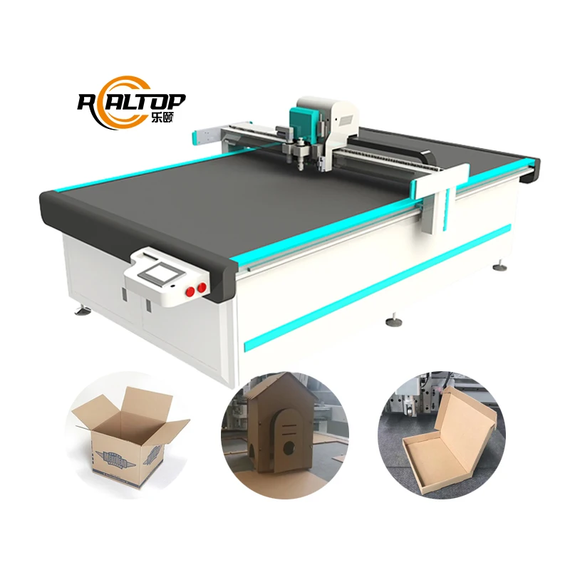
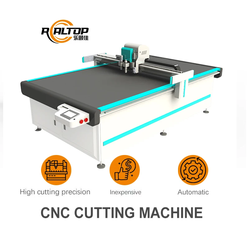
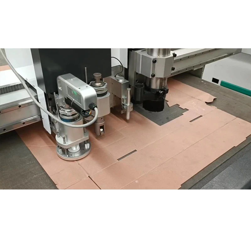
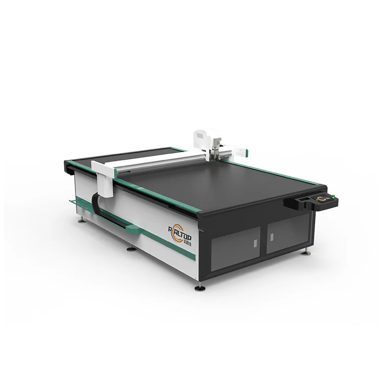
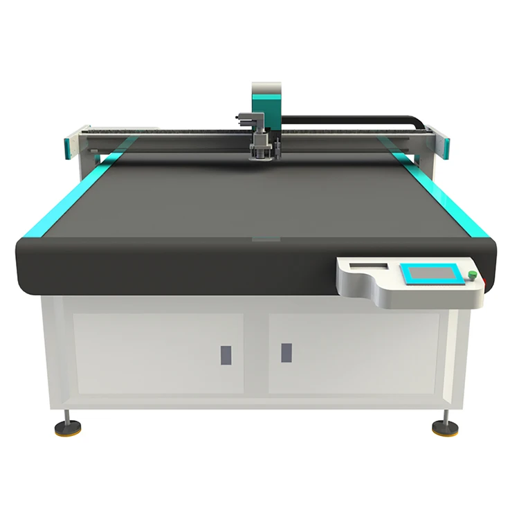
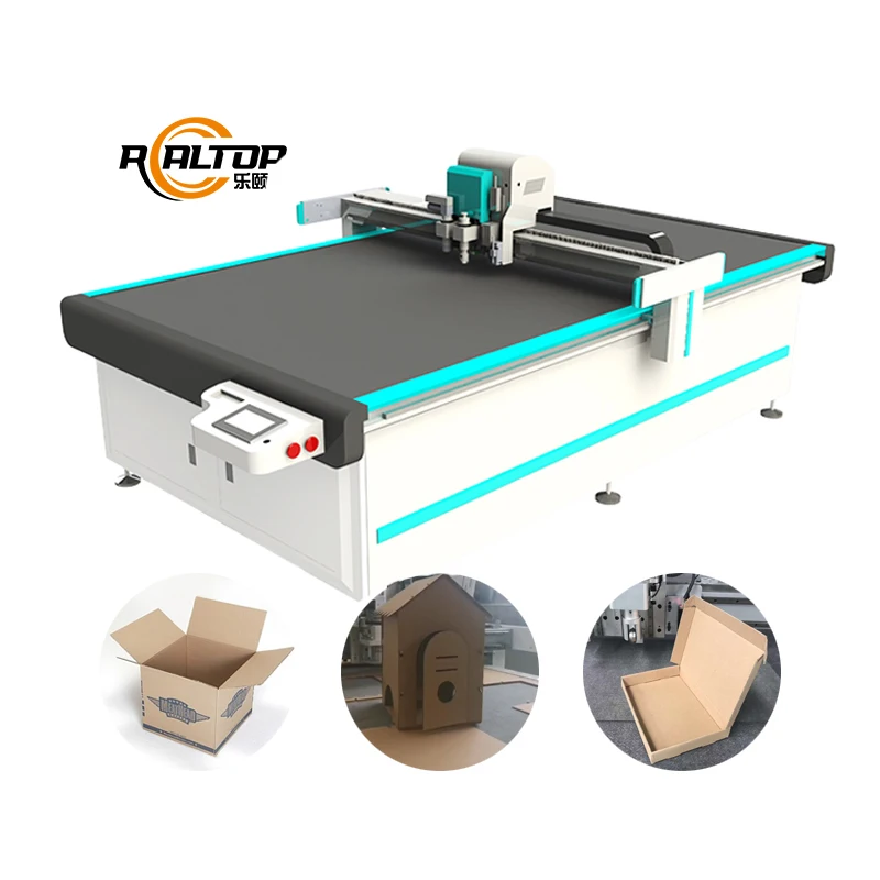
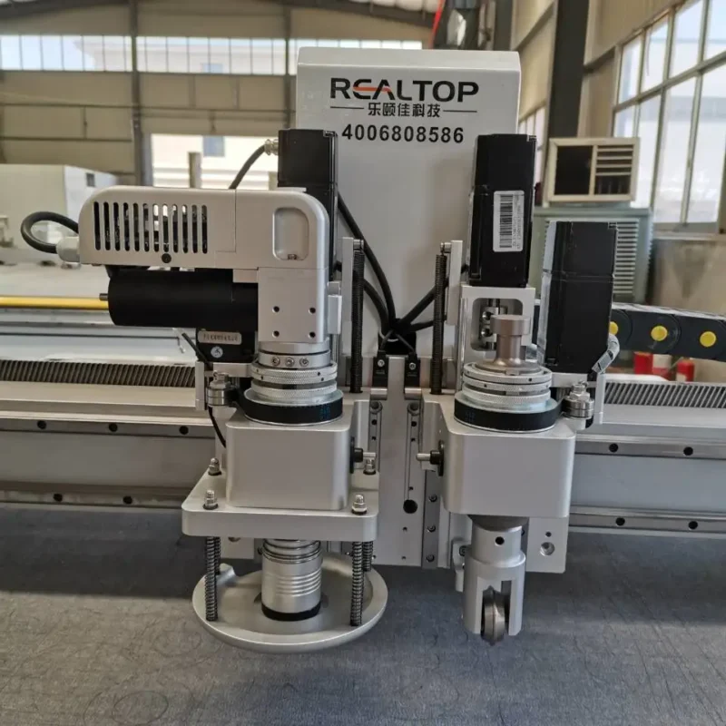
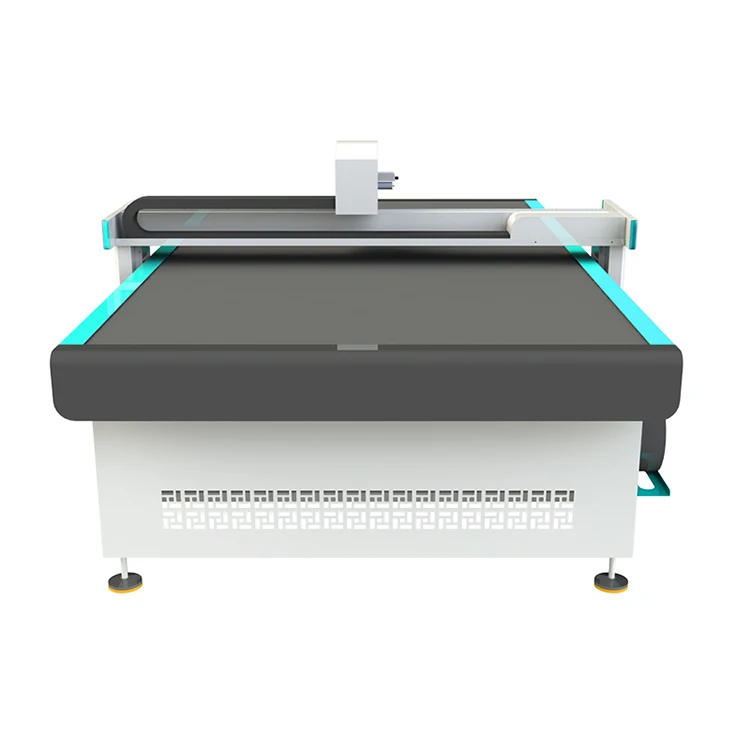
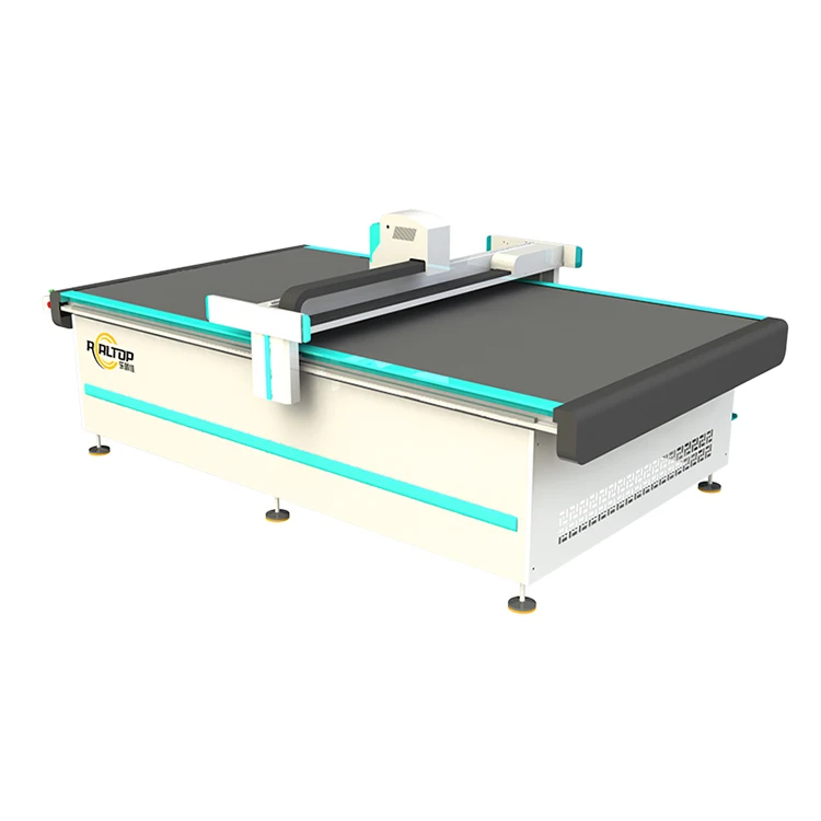
Tool Head Configuration Dictates Edge Quality — The RT-D2516/RT-S2516 platform is built around interchangeable knife heads rather than a fixed cutting method, allowing the machine to shift between full cutting, half cutting, creasing, and punching based on the substrate in front of it.
Technical Specifications
| Parameter | Value |
|---|---|
| Model | RT-D2516 / RT-S2516 |
| Working Area | 1600 × 2500 mm |
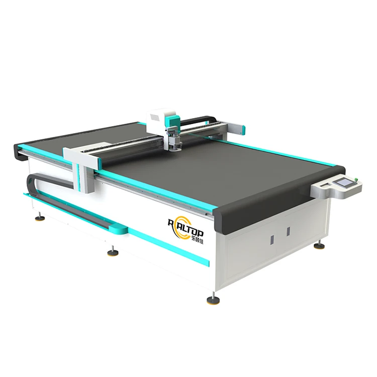
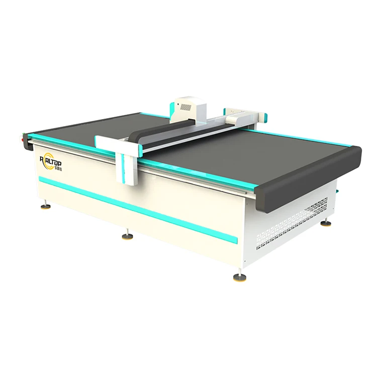
| Machine Size | 3450 × 2300 × 1250 mm |
| Rated Power | 9 kW |
| Maximum Cutting Thickness | ≤ 100 mm (varies with material density and type) |
| Translational Velocity | 800–1200 mm/s |
| Repeated Accuracy | ≤ 0.1 mm |
| Vacuum Pump | 7.5 kW integrated aviation aluminum shell |
| Table Type | Flat working table with vacuum adsorption |
| Transmission System | Digital servo motor, linear guide, synchronous belt, ball screw |
| Visual Positioning | Small CCD camera mark point, panoramic camera recognition, projection positioning |
| Instruction System | HP-GL compatible format |
| Voltage | 380V ± 10% |
| Control Language | English, Russian, Italian, Chinese; special languages configurable |
| Safety Device | Infrared sensors |
Application Suitability
| Application | Material or Output |
|---|---|
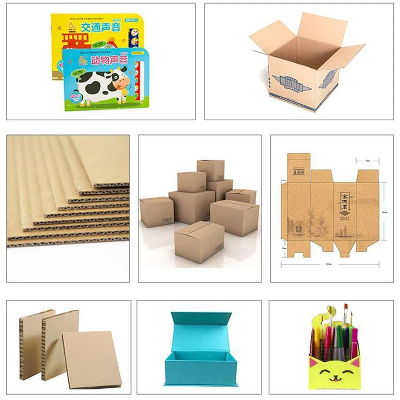
| Packaging and carton sample making | Corrugated board, greyboard, folding carton stock with creasing wheel and drag knife |
| Automotive interiors cutting | Synthetic leather, headliner fabric, sound-deadening foam composites |
| Garment and footwear production | Natural leather, textile layers, PU and PVC sheets |
| Gasket and sealing pad fabrication | Non-asbestos fiber, cork-rubber compound, PTFE sheet |
| Graphic advertising and printing | Vinyl film, self-adhesive board, foam PVC with CCD contour recognition |
| Composite and foam processing | Multi-layer sponge, EVA foam, honeycomb core with high-power vibrating knife |
When "Working Area" Is the Wrong Starting Point
A buyer often leads with table size, but a CNC oscillating knife cutting machine manufacturer knows the real question is what sits on that table. The cutting head and vacuum zoning must be chosen before the frame is built, not after. I have watched production lines stall because a machine was ordered for a 1600 × 2500 mm bed without anyone confirming the substrate density or the tool pressure required to push through it. When the material turns out to be harder or thicker than assumed, the knif*ges and scrapped batches [NEED_CITE: material density versus cutting force requirements in digital knife cutting].
Knife Heads and Material Matching
The multifunctional head on this system accepts Swiss-imported blades capable of vibration full cutting, vibration half cutting, and cursor location. That versatility matters when a single shop runs both rigid greyboard for cake boxes and flexible PU for shoe uppers on the same shift. A drag knife produces clean scored lines on corrugated stock, while an oscillating knife slices through multi-layer foam without crushing the cell structure. Choosing the wrong head for the substrate is the most common reason buyers report poor edge quality after installation.
Visual Positioning for Printed Contours
When cutting pre-printed materials like vinyl signage or die-cut packaging samples, the small CCD camera locates fiducial marks and adjusts the cutting path in real time. The panoramic camera option covers the entire bed in a single scan, which reduces setup time on jobs with multiple printed sheets laid out across the working area [NEED_CITE: CCD mark recognition accuracy on printed substrates at production speed]. Without this, operators manually align each sheet, and registration drift accumulates across a long run.
Reading the Specification Sheet Correctly
The 7.5 kW vacuum pump with integrated aviation aluminum shell delivers suction through a zoned table surface. Zoning matters because a small gasket part will lift and shift if the entire table is pulling air equally; isolating vacuum to the active cutting zone holds the part flat. The repeated accuracy of ≤ 0.1 mm depends on the Taiwan Hiwin linear guide and ball screw maintaining alignment under lateral cutting forces, which is why the transmission system specification is as important as the head itself. The Delta servo motor and Germany-imported conveyor belt support continuous feeding for high-volume fabric or textile runs, but the throughput depends entirely on material thickness, part geometry, and nesting density — none of which are fixed machine constants.
The Cost of Skipping a Material Trial
A packaging producer ordered a flatbed cutter based on sample cutting done on standard E-flute corrugated board. When production started on double-wall board with higher crush resistance, the standard oscillating knife could not complete the cut at line speed. The operator slowed the feed rate, throughput dropped, and the shop missed delivery windows for two consecutive orders [NEED_CITE: cutting speed versus material crush resistance in corrugated board processing]. Running a trial on the actual production material — including the thickest stock planned for the next twelve months — catches these mismatches before the purchase order is signed.
Why Configure Through One Manufacturer
Tool head selection, vacuum zoning, CCD option, and control language are not catalog checkboxes; they interact. A larger working area increases the vacuum requirement, which changes the pump specification. A higher cutting speed on dense material demands a stiffer frame to hold the ≤ 0.1 mm tolerance. Keeping design and production under one roof means these dependencies are resolved during engineering, not discovered on the buyer’s floor during commissioning. The in-house design team reviews the material sample cutting report alongside the tool head and table configuration list before the machine enters the build queue.
Documentation & Verification
- Machine specification sheet listing the exact tool heads and vacuum zone map configured for your material
- Electrical schematic confirming 380V ± 10% wiring and servo motor circuit layout
- Sample cutting report on your submitted material showing edge quality and achievable feed rate
- Factory test record documenting repeated accuracy and CCD registration performance before packing
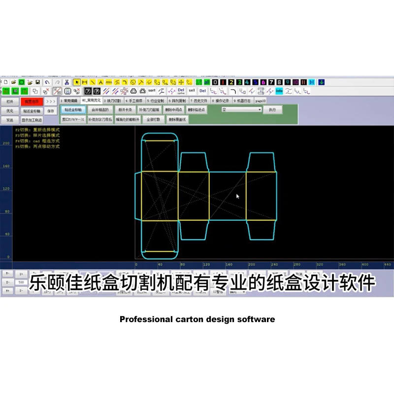
- Software licence note confirming HP-GL compatible format and file import workflow
- Spare parts list matching the specific knife blades, vacuum seals, and belts installed on your unit
Installation, Commissioning & Support
- Foundation must support the 3450 × 2300 × 1250 mm footprint with level tolerance for the linear guide system
- Dedicated 380V ± 10% circuit rated for the 9 kW total load including the 7.5 kW vacuum pump
- Machine ships partially assembled; vacuum table and gantry require on-site alignment and belt tensioning
- First-run parameter setting includes vacuum zone isolation, servo tuning, and CCD calibration on your printed sheets
- Operator training covers tool head changeover procedures and HP-GL file nesting workflow
- Wear-item schedule specifies replacement intervals for oscillating knife blades, vacuum seals, and conveyor belt segments
What to Include With Your Inquiry
Share the specific materials you plan to cut — type, thickness range, and whether they arrive in sheet or roll form — along with your typical part geometry and daily volume target. Confirm your facility voltage and frequency, the control language your operators need, and whether your existing design software exports HP-GL compatible files or requires a format conversion step. If you have printed material that needs contour recognition, send a sample sheet so the CCD calibration can be validated before the machine ships.
Frequently Asked Questions
Q: How do I determine whether knife cutting or laser cutting is the right method for my material?
A: Knife cutting suits materials that melt, discolor, or produce hazardous fumes under laser heat — foam, PVC, multi-layer composites, and thick leather. Laser cutting works better on thin acrylic, wood veneer, and textiles where a sealed edge is desirable. The same manufacturer builds both systems, so the recommendation is based on your material test rather than pushing one technology.
Q: Which tool head configuration matches my material thickness and edge quality requirements?
A: An oscillating knife handles dense board and foam up to the maximum cutting thickness without crushing. A drag knife scores and cuts thinner corrugated and folding carton stock. A creasing wheel produces fold lines on packaging samples. The head is specified after your material sample is test-cut, not guessed from a catalog table.
Q: What CCD camera positioning options are available for printed contour recognition at production speed?
A: The small CCD camera locates individual fiducial marks for high-accuracy single-sheet work. The panoramic camera scans the full bed to register multiple sheets in one pass, reducing manual alignment. Both options correct for print-to-cut drift caused by material stretch or feed variation during the run.
Q: How is vacuum table zoning configured for small parts to prevent material lift during cutting?
A: The 7.5 kW vacuum pump feeds a zoned table surface. During cutting, only the active zone under the knife head is energized, concentrating suction on the part being processed. This prevents small gaskets or narrow strips from lifting at the edges when the knife exits the cut path.
Tool Head Configuration Dictates Edge Quality — The RT-D2516/RT-S2516 platform is built around interchangeable knife heads rather than a fixed cutting method, allowing the machine to shift between full cutting, half cutting, creasing, and punching based on the substrate in front of it.
Technical Specifications
| Parameter | Value |
|---|---|
| Model | RT-D2516 / RT-S2516 |
| Working Area | 1600 × 2500 mm |
| Machine Size | 3450 × 2300 × 1250 mm |
| Rated Power | 9 kW |
| Maximum Cutting Thickness | ≤ 100 mm (varies with material density and type) |
| Translational Velocity | 800–1200 mm/s |
| Repeated Accuracy | ≤ 0.1 mm |
| Vacuum Pump | 7.5 kW integrated aviation aluminum shell |
| Table Type | Flat working table with vacuum adsorption |
| Transmission System | Digital servo motor, linear guide, synchronous belt, ball screw |
| Visual Positioning | Small CCD camera mark point, panoramic camera recognition, projection positioning |
| Instruction System | HP-GL compatible format |
| Voltage | 380V ± 10% |
| Control Language | English, Russian, Italian, Chinese; special languages configurable |
| Safety Device | Infrared sensors |
Application Suitability
| Application | Material or Output |
|---|---|
| Packaging and carton sample making | Corrugated board, greyboard, folding carton stock with creasing wheel and drag knife |
| Automotive interiors cutting | Synthetic leather, headliner fabric, sound-deadening foam composites |
| Garment and footwear production | Natural leather, textile layers, PU and PVC sheets |
| Gasket and sealing pad fabrication | Non-asbestos fiber, cork-rubber compound, PTFE sheet |
| Graphic advertising and printing | Vinyl film, self-adhesive board, foam PVC with CCD contour recognition |
| Composite and foam processing | Multi-layer sponge, EVA foam, honeycomb core with high-power vibrating knife |
When "Working Area" Is the Wrong Starting Point
A buyer often leads with table size, but a CNC oscillating knife cutting machine manufacturer knows the real question is what sits on that table. The cutting head and vacuum zoning must be chosen before the frame is built, not after. I have watched production lines stall because a machine was ordered for a 1600 × 2500 mm bed without anyone confirming the substrate density or the tool pressure required to push through it. When the material turns out to be harder or thicker than assumed, the knif*ges and scrapped batches [NEED_CITE: material density versus cutting force requirements in digital knife cutting].
Knife Heads and Material Matching
The multifunctional head on this system accepts Swiss-imported blades capable of vibration full cutting, vibration half cutting, and cursor location. That versatility matters when a single shop runs both rigid greyboard for cake boxes and flexible PU for shoe uppers on the same shift. A drag knife produces clean scored lines on corrugated stock, while an oscillating knife slices through multi-layer foam without crushing the cell structure. Choosing the wrong head for the substrate is the most common reason buyers report poor edge quality after installation.
Visual Positioning for Printed Contours
When cutting pre-printed materials like vinyl signage or die-cut packaging samples, the small CCD camera locates fiducial marks and adjusts the cutting path in real time. The panoramic camera option covers the entire bed in a single scan, which reduces setup time on jobs with multiple printed sheets laid out across the working area [NEED_CITE: CCD mark recognition accuracy on printed substrates at production speed]. Without this, operators manually align each sheet, and registration drift accumulates across a long run.
Reading the Specification Sheet Correctly
The 7.5 kW vacuum pump with integrated aviation aluminum shell delivers suction through a zoned table surface. Zoning matters because a small gasket part will lift and shift if the entire table is pulling air equally; isolating vacuum to the active cutting zone holds the part flat. The repeated accuracy of ≤ 0.1 mm depends on the Taiwan Hiwin linear guide and ball screw maintaining alignment under lateral cutting forces, which is why the transmission system specification is as important as the head itself. The Delta servo motor and Germany-imported conveyor belt support continuous feeding for high-volume fabric or textile runs, but the throughput depends entirely on material thickness, part geometry, and nesting density — none of which are fixed machine constants.
The Cost of Skipping a Material Trial
A packaging producer ordered a flatbed cutter based on sample cutting done on standard E-flute corrugated board. When production started on double-wall board with higher crush resistance, the standard oscillating knife could not complete the cut at line speed. The operator slowed the feed rate, throughput dropped, and the shop missed delivery windows for two consecutive orders [NEED_CITE: cutting speed versus material crush resistance in corrugated board processing]. Running a trial on the actual production material — including the thickest stock planned for the next twelve months — catches these mismatches before the purchase order is signed.
Why Configure Through One Manufacturer
Tool head selection, vacuum zoning, CCD option, and control language are not catalog checkboxes; they interact. A larger working area increases the vacuum requirement, which changes the pump specification. A higher cutting speed on dense material demands a stiffer frame to hold the ≤ 0.1 mm tolerance. Keeping design and production under one roof means these dependencies are resolved during engineering, not discovered on the buyer’s floor during commissioning. The in-house design team reviews the material sample cutting report alongside the tool head and table configuration list before the machine enters the build queue.
Documentation & Verification
- Machine specification sheet listing the exact tool heads and vacuum zone map configured for your material
- Electrical schematic confirming 380V ± 10% wiring and servo motor circuit layout
- Sample cutting report on your submitted material showing edge quality and achievable feed rate
- Factory test record documenting repeated accuracy and CCD registration performance before packing
- Software licence note confirming HP-GL compatible format and file import workflow
- Spare parts list matching the specific knife blades, vacuum seals, and belts installed on your unit
Installation, Commissioning & Support
- Foundation must support the 3450 × 2300 × 1250 mm footprint with level tolerance for the linear guide system
- Dedicated 380V ± 10% circuit rated for the 9 kW total load including the 7.5 kW vacuum pump
- Machine ships partially assembled; vacuum table and gantry require on-site alignment and belt tensioning
- First-run parameter setting includes vacuum zone isolation, servo tuning, and CCD calibration on your printed sheets
- Operator training covers tool head changeover procedures and HP-GL file nesting workflow
- Wear-item schedule specifies replacement intervals for oscillating knife blades, vacuum seals, and conveyor belt segments
What to Include With Your Inquiry
Share the specific materials you plan to cut — type, thickness range, and whether they arrive in sheet or roll form — along with your typical part geometry and daily volume target. Confirm your facility voltage and frequency, the control language your operators need, and whether your existing design software exports HP-GL compatible files or requires a format conversion step. If you have printed material that needs contour recognition, send a sample sheet so the CCD calibration can be validated before the machine ships.
Frequently Asked Questions
Q: How do I determine whether knife cutting or laser cutting is the right method for my material?
A: Knife cutting suits materials that melt, discolor, or produce hazardous fumes under laser heat — foam, PVC, multi-layer composites, and thick leather. Laser cutting works better on thin acrylic, wood veneer, and textiles where a sealed edge is desirable. The same manufacturer builds both systems, so the recommendation is based on your material test rather than pushing one technology.
Q: Which tool head configuration matches my material thickness and edge quality requirements?
A: An oscillating knife handles dense board and foam up to the maximum cutting thickness without crushing. A drag knife scores and cuts thinner corrugated and folding carton stock. A creasing wheel produces fold lines on packaging samples. The head is specified after your material sample is test-cut, not guessed from a catalog table.
Q: What CCD camera positioning options are available for printed contour recognition at production speed?
A: The small CCD camera locates individual fiducial marks for high-accuracy single-sheet work. The panoramic camera scans the full bed to register multiple sheets in one pass, reducing manual alignment. Both options correct for print-to-cut drift caused by material stretch or feed variation during the run.
Q: How is vacuum table zoning configured for small parts to prevent material lift during cutting?
A: The 7.5 kW vacuum pump feeds a zoned table surface. During cutting, only the active zone under the knife head is energized, concentrating suction on the part being processed. This prevents small gaskets or narrow strips from lifting at the edges when the knife exits the cut path.
商品评价
There are no reviews yet.