

Fast Delivery
Quick, reliable shipping to any location.

Free & easy returns
Return this item by mail or in store within 90 days for a full refund.
Complete Cutting Method Evaluation — we specify oscillating knife, drag knife, or laser based on the buyer’s actual composite layup and thickness, not by catalog default.
Technical Specifications
| Parameter | Value |
|---|---|
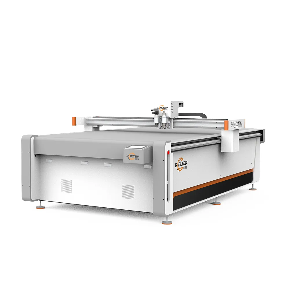
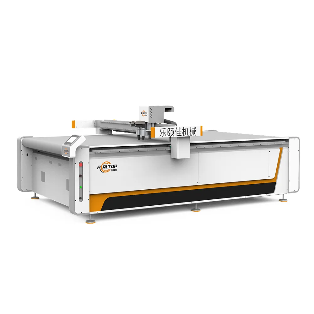
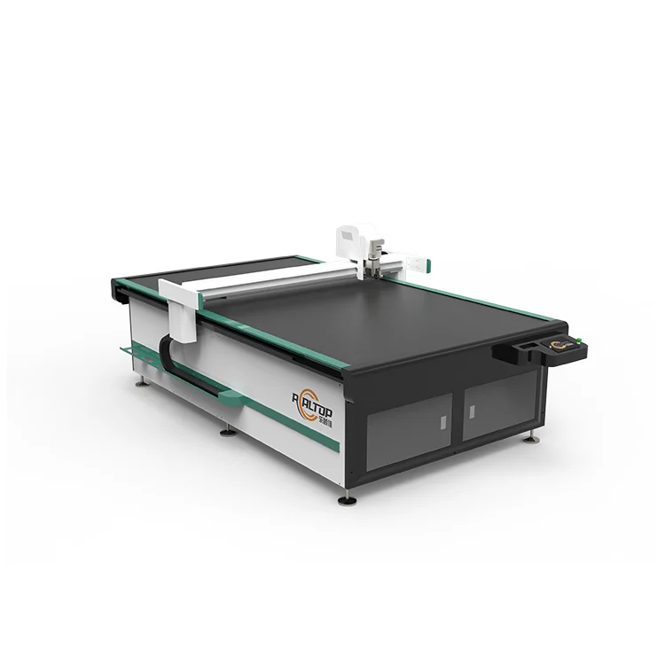
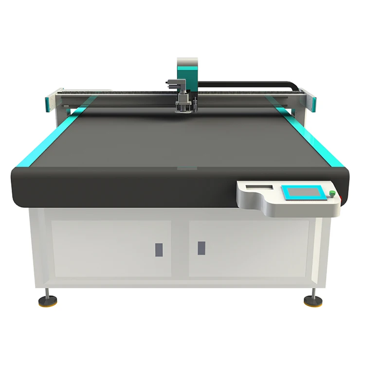
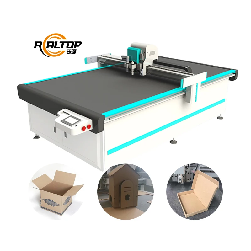
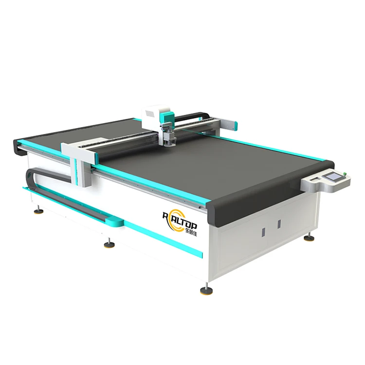
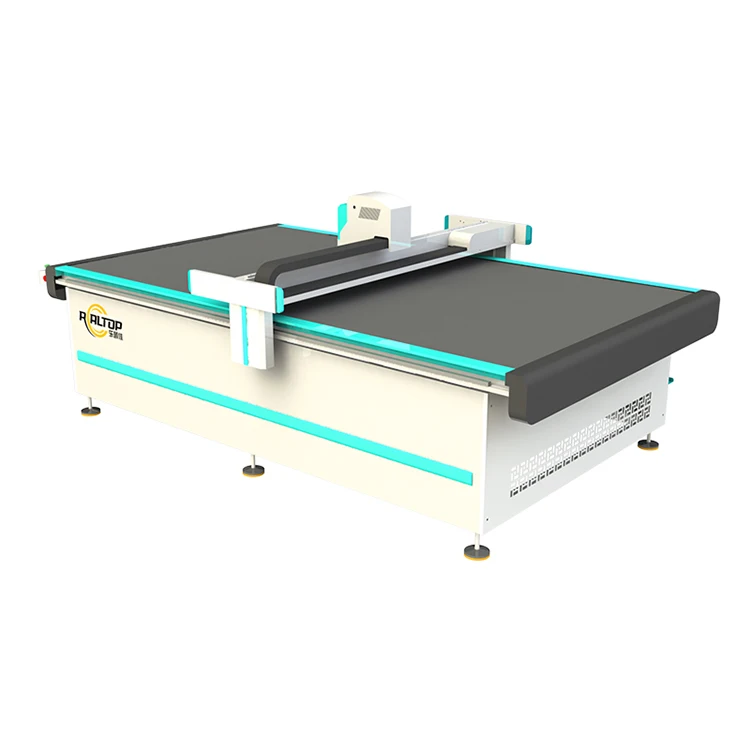
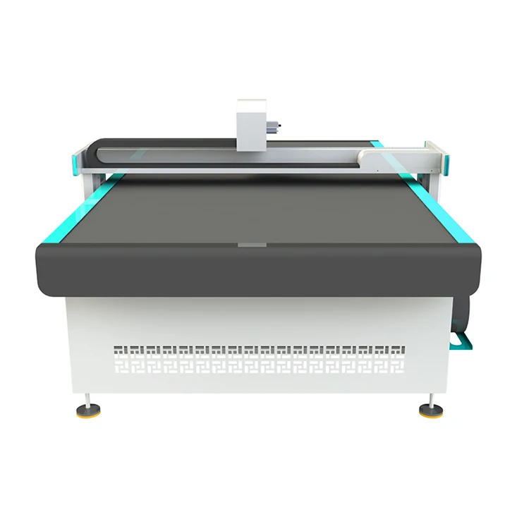
| Product Type | CNC Oscillating Knife Cutting Machine |
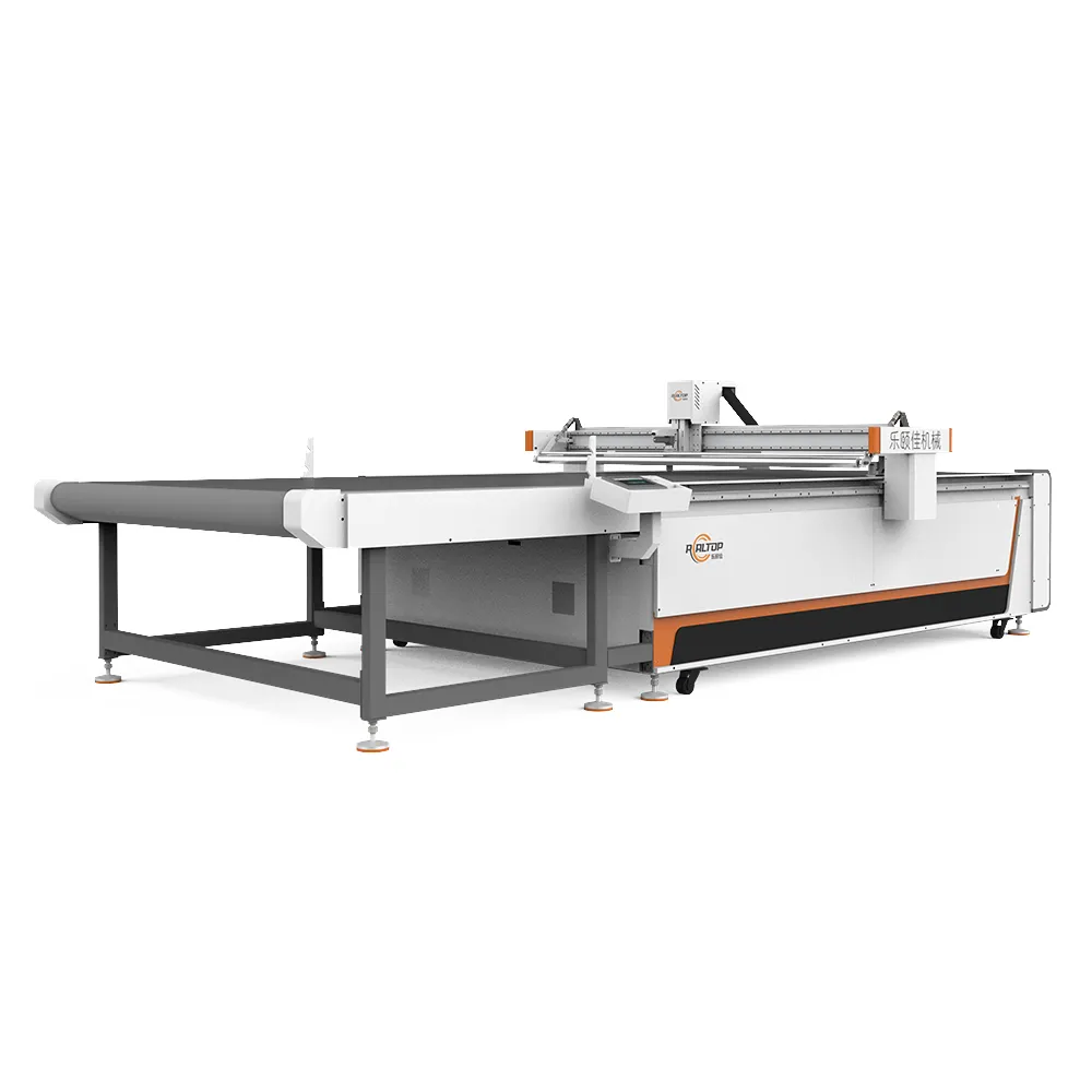
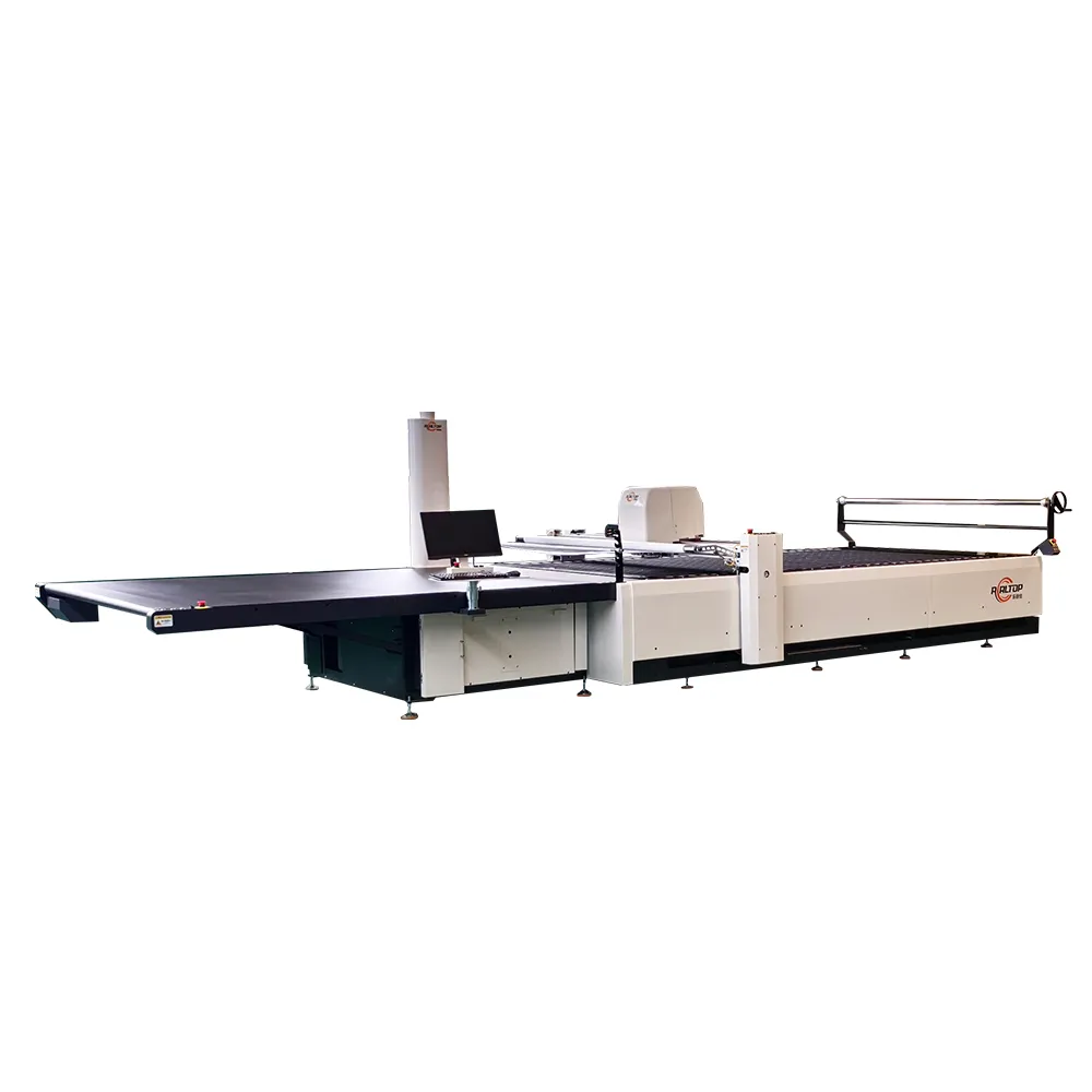
| Effective Cutting Area | 2500×1600 mm / 2500×2200 mm / 3000×2200 mm |
| Maximum Speed | 2000 mm/s (basis not stated in source — confirm material and thickness) |
| Reset Accuracy | ±0.1 mm |
| Cutting Thickness | ≤40 mm (basis not stated in source — confirm composite type and density) |
| Table Type | Automatic feeding with conveyor and industrial glass fiber tension belt |
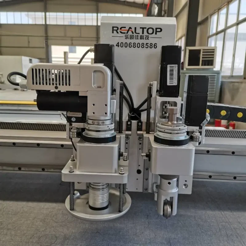
| Tool Head Options | Conventional vibrating knife, Servo vibrating knife, Pneumatic knife, Circular knife, Marking pen |
| Control System | REALTOP customized high-speed control system |
| Visual Positioning | Panoramic visual positioning for automatic edge and template cutting |
| Data Format | dxf, plt, ai, pdf |
| Voltage | 380V / 220V (frequency to be confirmed) |
| Safety Device | Infrared blocking stop and anti-collision protection |
| Wiring | Oxygen-free copper shielded wire |
| Bed Treatment | Quenched to eliminate internal stress |
| Noise Design | Exclusive silent design |
Application Suitability
| Application | Material or Output |
|---|---|
| Composite panel trimming | Carbon fiber sheets, fiberglass foam sandwich panels, aramid honeycomb cores |
| Automotive interior fabrication | Fiberglass-reinforced plastic panels, headliner substrates, acoustic insulation laminates |
| Aerospace composite layup | Pre-preg carbon fabric, glass fiber textile stacks, structural foam cores |
| Gasket and seal production | Non-asbestos fiber sheets, cork-rubber composite rolls, PTFE-filled composites |
| Marine composite hull work | Fiberglass woven roving, PVC foam core sandwich, epoxy-laminated panels |
| Sporting goods manufacturing | Carbon fiber prepreg, Kevlar fabric, closed-cell foam padding |
Why the Cutting Method Must Be Decided Before the Working Area
Matching the cutting method to the composite material eliminates costly re-configuration after delivery.
I once shipped what looked like a perfectly configured unit to a Middle East buyer — the factory ran standard carbon fiber plate trials and the edges came out clean. But the buyer’s actual daily work involved fiberglass foam sandwich board, and the tool head we selected could not hold up against the abrasive glass fibers. Parameters went out the window, and we spent two weeks rebuilding the cutting solution from scratch. A CNC Oscillating Knife Cutting Machine manufacturer should never let a buyer select a machine based on table size alone [NEED_CITE: composite material hardness and abrasiveness vary across layup types]. The composite’s fiber orientation, resin system, and core material all dictate which tool head and oscillation frequency will produce a usable edge.
Surveying Knife Versus Laser Across Composite Types
This full-range catalogue exists so buyers can compare oscillating knife, drag knife, and laser cutting methods before narrowing down. Oscillating knife heads handle layered composites well because the vertical vibration shears through fiber and resin without melting or fraying the edges. For thinner prepreg fabrics and soft foam cores, a drag knife or circular knife may deliver cleaner contours at higher traverse rates. Laser cutting enters the conversation only when the composite is non-metallic and the edge sealing benefit outweighs the thermal impact on the resin matrix.
Panoramic Visual Positioning for Printed Contour Work
When composite parts carry printed registration marks or nested template outlines, the panoramic visual positioning system reads those references and adjusts the cutting path in real time. This matters for automotive interior skins where a printed grain pattern must align with the trim line, or for signage substrates where contour accuracy determines whether the finished piece fits its mounting frame. The system supports automatic edge detection and template matching, reducing the manual alignment steps that otherwise slow down short-run production.
Interpreting Specifications That Actually Affect Composite Output
The three available working areas — 2500×1600 mm, 2500×2200 mm, and 3000×2200 mm — cover everything from automotive interior panels to large marine hull sections. But working area is only the starting point. The cutting thickness specification of ≤40 mm must be validated against the actual composite density and fiber content; a 40 mm foam core cuts differently from a 40 mm solid glass fiber laminate. Tool head selection is the next critical variable: a servo vibrating knife delivers higher-frequency oscillation suitable for dense fiberglass, while a pneumatic knife provides the downward force needed for thick honeycomb cores. The automatic conveyor table with its glass fiber tension belt supports continuous roll-fed composite textile workflows, and the oxygen-free copper shielded wiring reduces signal interference that could otherwise affect positioning accuracy over long production runs [NEED_CITE: signal interference effects on CNC positioning in industrial environments].
The Hidden Cost of Specifying the Wrong Tool Head
When a buyer selects a conventional vibrating knife for a material that demands a servo variant, the edge quality degrades gradually over the first few production hours. Fiber pull-out increases, tool wear accelerates, and the operator begins compensating with slower feed rates. Nobody notices until the first batch rejection [NEED_CITE: tool wear patterns on abrasive composite materials]. By that point, the downtime for re-tooling and re-programming has already consumed more value than the price difference between the two tool heads.
Why This Range Exists for Composite Buyers
In-house design covering both knife and laser technologies means a buyer can evaluate the full spectrum of cutting methods against their specific composite layup rather than being pushed toward whichever machine is in stock. Tool head and table configuration are specified per material and production volume — no generic package deals. CCD-style panoramic positioning is tested on the buyer’s actual printed substrate before the order is finalized. Software compatibility with dxf, plt, ai, and pdf formats is confirmed in advance so there are no surprises on day one of production. Sample cutting on the buyer’s own composite material is available before any commitment is made.
Documentation & Verification
- Machine specification sheet comparing all three working area formats and tool head options
- Sample cutting report produced on buyer’s actual composite material before order confirmation
- Tool head and table configuration list matched to specific fiber type and thickness
- Electrical schematic with voltage and frequency confirmed for destination country
- Software licence and file format compatibility note covering dxf, plt, ai, pdf workflows
- Factory test record documenting cutting accuracy and edge quality on specified material
Installation, Commissioning & Support
- Floor leveling and anchoring requirements for the 3000×2200 mm format conveyor table
- Dedicated circuit provision for 380V or 220V supply with confirmed frequency
- Conveyor belt tensioning and tracking calibration during first-day commissioning
- Panoramic visual positioning alignment using buyer’s printed composite templates
- Tool head oscillation frequency tuning matched to specific composite density
- Spare oscillating blades and circular knife consumables included for initial production run
What We Need to Configure Your Machine Correctly
Send us the composite material type, layup sequence, and total thickness you cut most often. Include your typical sheet or roll dimensions and daily part volume. Tell us your facility voltage and frequency, and whether your operators need a specific control language. If your parts rely on printed contour marks, share a sample file so we can verify the panoramic positioning on your exact artwork.
Frequently Asked Questions
Q: Should I choose oscillating knife or laser for fiberglass sandwich panels?
A: Oscillating knife is typically preferred for fiberglass sandwich panels because it cuts through the glass fiber and foam core without generating heat that would melt or char the resin. Laser cutting can work on thinner non-metallic composites where edge sealing is beneficial, but thermal damage to the resin matrix is a risk on thicker layups. We run sample cuts on your actual material to confirm the method.
Q: How do I select the right working area from the three available formats?
A: Start with your largest sheet or panel dimension, then add clearance for the tool head sweep and clamping zones. The 2516 format suits automotive interior trim panels, while the 3022 handles full-size marine hull sections. Conveyor-fed workflows also benefit from a longer table to accommodate roll-fed material advance.
Q: Which tool head works best for carbon fiber prepreg fabric?
A: A servo vibrating knife generally delivers the cleanest edge on carbon fiber prepreg because the higher oscillation frequency shears the fibers without fraying. For very thin single-ply fabrics, a drag knife may also perform well. We test multiple tool heads on your material sample before recommending a configuration.
Q: What printed mark types does the panoramic visual positioning support?
A: The system reads standard registration marks, fiducial dots, and printed contour outlines on composite substrates. Recognition performance depends on mark contrast, size, and spacing relative to the camera field of view. We verify tracking accuracy at production speed using your actual printed artwork before the order is finalized.
Q: Is the conveyor automatic feeding table better than a static vacuum table for composites?
A: Conveyor feeding suits roll-fed composite textiles where continuous material advance reduces loading time between cuts. A static vacuum table with zoned suction is better for rigid composite panels and small parts that need firm hold-down during cutting. The choice depends on your material format and part geometry.
Complete Cutting Method Evaluation — we specify oscillating knife, drag knife, or laser based on the buyer’s actual composite layup and thickness, not by catalog default.
Technical Specifications
| Parameter | Value |
|---|---|
| Product Type | CNC Oscillating Knife Cutting Machine |
| Effective Cutting Area | 2500×1600 mm / 2500×2200 mm / 3000×2200 mm |
| Maximum Speed | 2000 mm/s (basis not stated in source — confirm material and thickness) |
| Reset Accuracy | ±0.1 mm |
| Cutting Thickness | ≤40 mm (basis not stated in source — confirm composite type and density) |
| Table Type | Automatic feeding with conveyor and industrial glass fiber tension belt |
| Tool Head Options | Conventional vibrating knife, Servo vibrating knife, Pneumatic knife, Circular knife, Marking pen |
| Control System | REALTOP customized high-speed control system |
| Visual Positioning | Panoramic visual positioning for automatic edge and template cutting |
| Data Format | dxf, plt, ai, pdf |
| Voltage | 380V / 220V (frequency to be confirmed) |
| Safety Device | Infrared blocking stop and anti-collision protection |
| Wiring | Oxygen-free copper shielded wire |
| Bed Treatment | Quenched to eliminate internal stress |
| Noise Design | Exclusive silent design |
Application Suitability
| Application | Material or Output |
|---|---|
| Composite panel trimming | Carbon fiber sheets, fiberglass foam sandwich panels, aramid honeycomb cores |
| Automotive interior fabrication | Fiberglass-reinforced plastic panels, headliner substrates, acoustic insulation laminates |
| Aerospace composite layup | Pre-preg carbon fabric, glass fiber textile stacks, structural foam cores |
| Gasket and seal production | Non-asbestos fiber sheets, cork-rubber composite rolls, PTFE-filled composites |
| Marine composite hull work | Fiberglass woven roving, PVC foam core sandwich, epoxy-laminated panels |
| Sporting goods manufacturing | Carbon fiber prepreg, Kevlar fabric, closed-cell foam padding |
Why the Cutting Method Must Be Decided Before the Working Area
Matching the cutting method to the composite material eliminates costly re-configuration after delivery.
I once shipped what looked like a perfectly configured unit to a Middle East buyer — the factory ran standard carbon fiber plate trials and the edges came out clean. But the buyer’s actual daily work involved fiberglass foam sandwich board, and the tool head we selected could not hold up against the abrasive glass fibers. Parameters went out the window, and we spent two weeks rebuilding the cutting solution from scratch. A CNC Oscillating Knife Cutting Machine manufacturer should never let a buyer select a machine based on table size alone [NEED_CITE: composite material hardness and abrasiveness vary across layup types]. The composite’s fiber orientation, resin system, and core material all dictate which tool head and oscillation frequency will produce a usable edge.
Surveying Knife Versus Laser Across Composite Types
This full-range catalogue exists so buyers can compare oscillating knife, drag knife, and laser cutting methods before narrowing down. Oscillating knife heads handle layered composites well because the vertical vibration shears through fiber and resin without melting or fraying the edges. For thinner prepreg fabrics and soft foam cores, a drag knife or circular knife may deliver cleaner contours at higher traverse rates. Laser cutting enters the conversation only when the composite is non-metallic and the edge sealing benefit outweighs the thermal impact on the resin matrix.
Panoramic Visual Positioning for Printed Contour Work
When composite parts carry printed registration marks or nested template outlines, the panoramic visual positioning system reads those references and adjusts the cutting path in real time. This matters for automotive interior skins where a printed grain pattern must align with the trim line, or for signage substrates where contour accuracy determines whether the finished piece fits its mounting frame. The system supports automatic edge detection and template matching, reducing the manual alignment steps that otherwise slow down short-run production.
Interpreting Specifications That Actually Affect Composite Output
The three available working areas — 2500×1600 mm, 2500×2200 mm, and 3000×2200 mm — cover everything from automotive interior panels to large marine hull sections. But working area is only the starting point. The cutting thickness specification of ≤40 mm must be validated against the actual composite density and fiber content; a 40 mm foam core cuts differently from a 40 mm solid glass fiber laminate. Tool head selection is the next critical variable: a servo vibrating knife delivers higher-frequency oscillation suitable for dense fiberglass, while a pneumatic knife provides the downward force needed for thick honeycomb cores. The automatic conveyor table with its glass fiber tension belt supports continuous roll-fed composite textile workflows, and the oxygen-free copper shielded wiring reduces signal interference that could otherwise affect positioning accuracy over long production runs [NEED_CITE: signal interference effects on CNC positioning in industrial environments].
The Hidden Cost of Specifying the Wrong Tool Head
When a buyer selects a conventional vibrating knife for a material that demands a servo variant, the edge quality degrades gradually over the first few production hours. Fiber pull-out increases, tool wear accelerates, and the operator begins compensating with slower feed rates. Nobody notices until the first batch rejection [NEED_CITE: tool wear patterns on abrasive composite materials]. By that point, the downtime for re-tooling and re-programming has already consumed more value than the price difference between the two tool heads.
Why This Range Exists for Composite Buyers
In-house design covering both knife and laser technologies means a buyer can evaluate the full spectrum of cutting methods against their specific composite layup rather than being pushed toward whichever machine is in stock. Tool head and table configuration are specified per material and production volume — no generic package deals. CCD-style panoramic positioning is tested on the buyer’s actual printed substrate before the order is finalized. Software compatibility with dxf, plt, ai, and pdf formats is confirmed in advance so there are no surprises on day one of production. Sample cutting on the buyer’s own composite material is available before any commitment is made.
Documentation & Verification
- Machine specification sheet comparing all three working area formats and tool head options
- Sample cutting report produced on buyer’s actual composite material before order confirmation
- Tool head and table configuration list matched to specific fiber type and thickness
- Electrical schematic with voltage and frequency confirmed for destination country
- Software licence and file format compatibility note covering dxf, plt, ai, pdf workflows
- Factory test record documenting cutting accuracy and edge quality on specified material
Installation, Commissioning & Support
- Floor leveling and anchoring requirements for the 3000×2200 mm format conveyor table
- Dedicated circuit provision for 380V or 220V supply with confirmed frequency
- Conveyor belt tensioning and tracking calibration during first-day commissioning
- Panoramic visual positioning alignment using buyer’s printed composite templates
- Tool head oscillation frequency tuning matched to specific composite density
- Spare oscillating blades and circular knife consumables included for initial production run
What We Need to Configure Your Machine Correctly
Send us the composite material type, layup sequence, and total thickness you cut most often. Include your typical sheet or roll dimensions and daily part volume. Tell us your facility voltage and frequency, and whether your operators need a specific control language. If your parts rely on printed contour marks, share a sample file so we can verify the panoramic positioning on your exact artwork.
Frequently Asked Questions
Q: Should I choose oscillating knife or laser for fiberglass sandwich panels?
A: Oscillating knife is typically preferred for fiberglass sandwich panels because it cuts through the glass fiber and foam core without generating heat that would melt or char the resin. Laser cutting can work on thinner non-metallic composites where edge sealing is beneficial, but thermal damage to the resin matrix is a risk on thicker layups. We run sample cuts on your actual material to confirm the method.
Q: How do I select the right working area from the three available formats?
A: Start with your largest sheet or panel dimension, then add clearance for the tool head sweep and clamping zones. The 2516 format suits automotive interior trim panels, while the 3022 handles full-size marine hull sections. Conveyor-fed workflows also benefit from a longer table to accommodate roll-fed material advance.
Q: Which tool head works best for carbon fiber prepreg fabric?
A: A servo vibrating knife generally delivers the cleanest edge on carbon fiber prepreg because the higher oscillation frequency shears the fibers without fraying. For very thin single-ply fabrics, a drag knife may also perform well. We test multiple tool heads on your material sample before recommending a configuration.
Q: What printed mark types does the panoramic visual positioning support?
A: The system reads standard registration marks, fiducial dots, and printed contour outlines on composite substrates. Recognition performance depends on mark contrast, size, and spacing relative to the camera field of view. We verify tracking accuracy at production speed using your actual printed artwork before the order is finalized.
Q: Is the conveyor automatic feeding table better than a static vacuum table for composites?
A: Conveyor feeding suits roll-fed composite textiles where continuous material advance reduces loading time between cuts. A static vacuum table with zoned suction is better for rigid composite panels and small parts that need firm hold-down during cutting. The choice depends on your material format and part geometry.
商品评价
There are no reviews yet.