

Fast Delivery
Quick, reliable shipping to any location.

Free & easy returns
Return this item by mail or in store within 90 days for a full refund.
Custom tool head mapping — we match knife type, CCD recognition and vacuum zoning to your exact substrate before quoting the RTT-6080 series, so cutting depth and edge quality hold at your production speed rather than only during sample approval.
Technical Specifications
| Parameter | Value |
|---|---|
| Model | RTT6080 / RTT6080 Pro |
| Product Type | CNC Digital Die Cutting Plotter |
| Max Working Area | 600 mm × 800 mm |
| Tool Configuration (RTT6080) | Cutting tool, kiss cutting tool, creasing tool, CCD camera |
| Tool Configuration (RTT6080 Pro) | Cutting tool, kiss cutting tool, creasing tool, CCD camera, high speed oscillating knife |
| Max Cutting Speed | 1500 mm/s (basis not stated in source — confirm material / thickness) |
| Cutting Thickness (RTT6080) | ≤ 2 mm (basis not stated in source — confirm material type) |
| Cutting Thickness (RTT6080 Pro) | ≤ 5 mm (basis not stated in source — confirm material type) |
| Positioning Accuracy | 0.05 mm |
| File Format | DXF, PLT, PDF, AI |
| Transfer Method | Ethernet port |
| Rated Power | 3.2 kW (rated or peak not specified in source) |
| Voltage | 220 V / 380 V, 50 Hz |
| Control System | CNC (source value — verify against manufacturer catalog) |
| Assembly State | Fully assembled (source value — verify against manufacturer catalog) |
Application Suitability
| Application | Material or Output |
|---|---|
| Sticker and label die cutting | Self-adhesive vinyl, PET, BOPP, release liner stock |
| Short-run carton prototyping | Corrugated flute, single-face board, kraft liner |
| Packaging sample making | Folding carton board, greyboard, art paper laminates |
| Advertising and signage prototyping | Self-adhesive film, magnetic sheet, thin PVC board |
| Kiss cutting and creasing | Pressure-sensitive labels, window patching film |
Why the Cutting Thickness Claim Is Where Most Plotter Quotes Fall Apart
When sourcing a CNC Die Cutting Plotter manufacturer, the single number most often misunderstood is maximum cutting thickness, because the figure quoted is almost always a best-case laboratory value on a uniform, compliant material. The only thickness number that matters is the one measured on your actual stock, with your specific liner and adhesive combination, at the speed you intend to run. I have sat in workshops where a plotter was specified on working area alone, then watched the knife stall on a 1.2 mm PVC sticker that the datasheet said would cut at 2 mm, because the adhesive layer and release liner added stiffness the blade could not shear cleanly. The operator then slowed the feed and dropped pressure, which introduced drag marks on the printed face and forced a second pass that doubled cycle time [NEED_CITE: material stiffness and blade drag in pressure-sensitive substrates].
How the Tool Head Range Covers the Sticker-to-Sample Gap
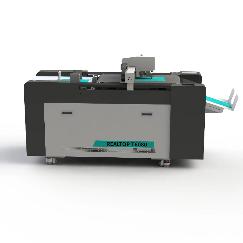
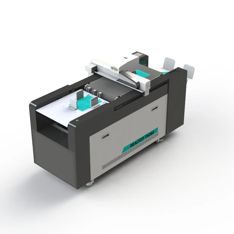
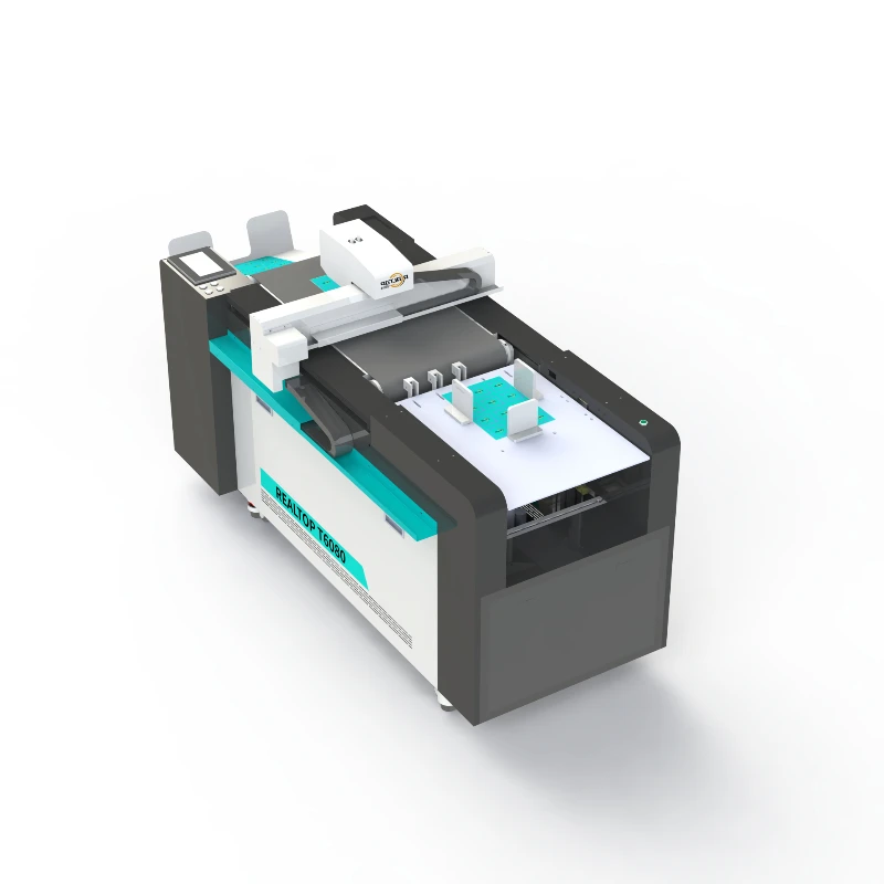
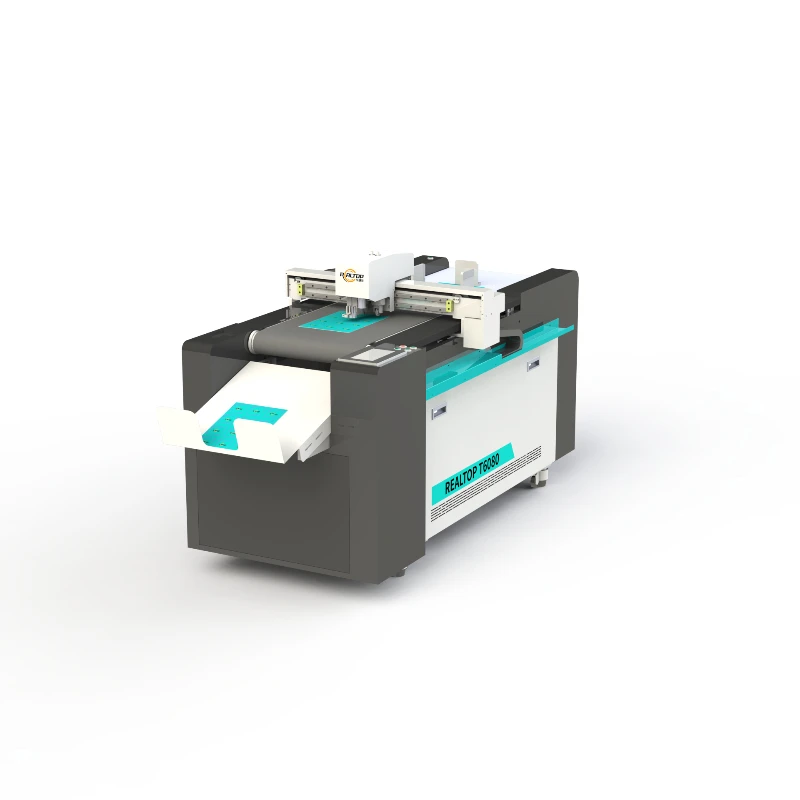
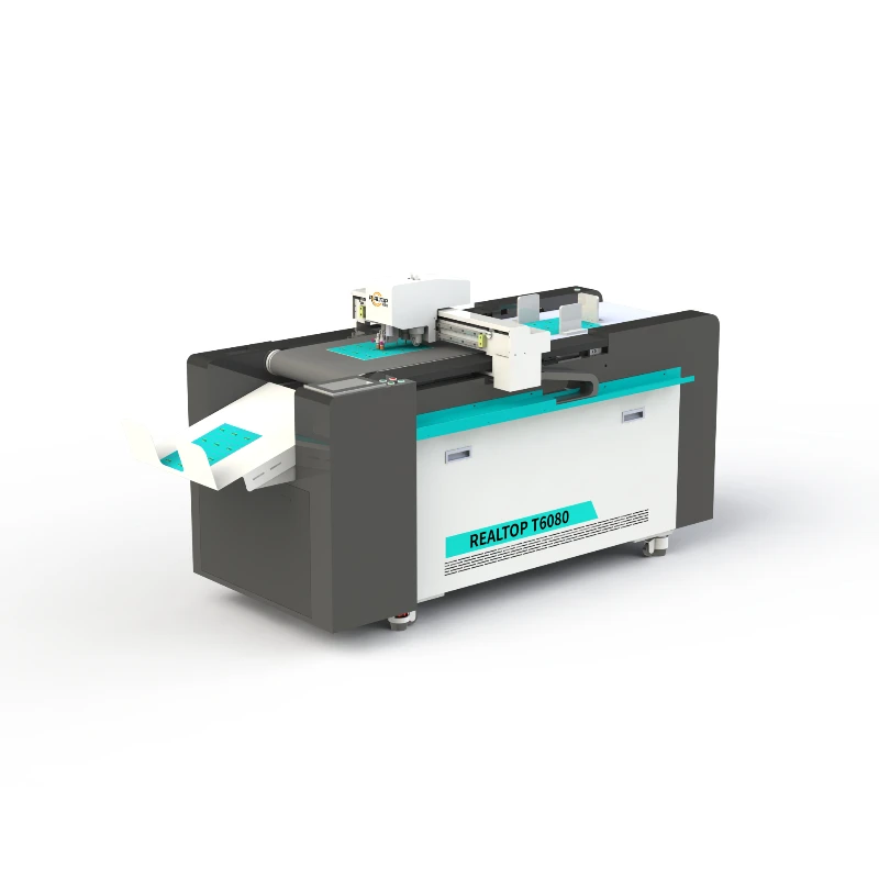
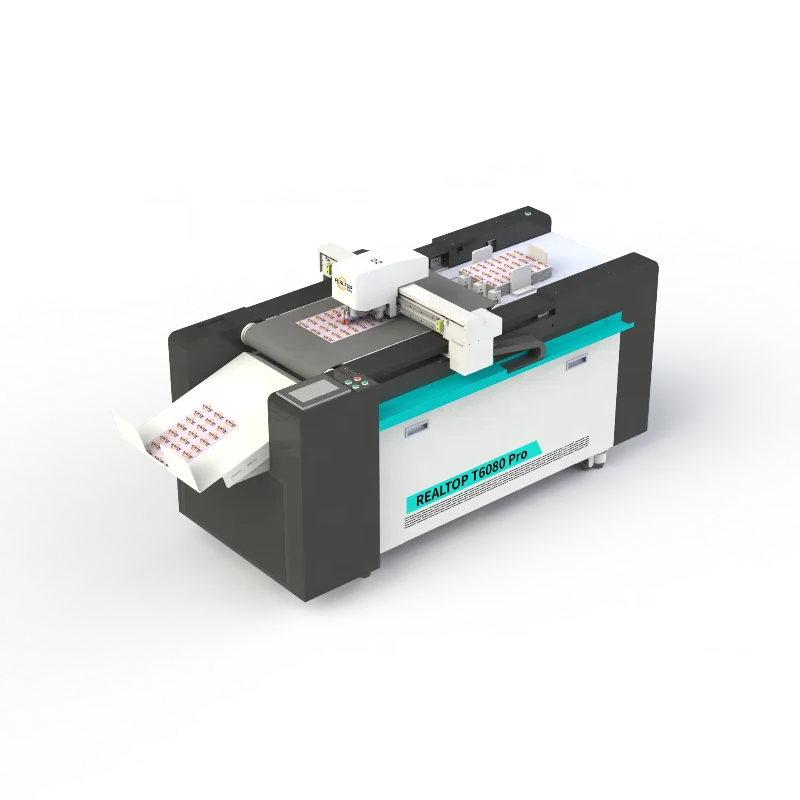
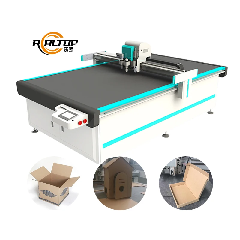
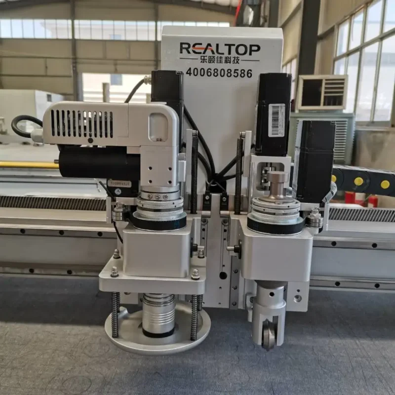
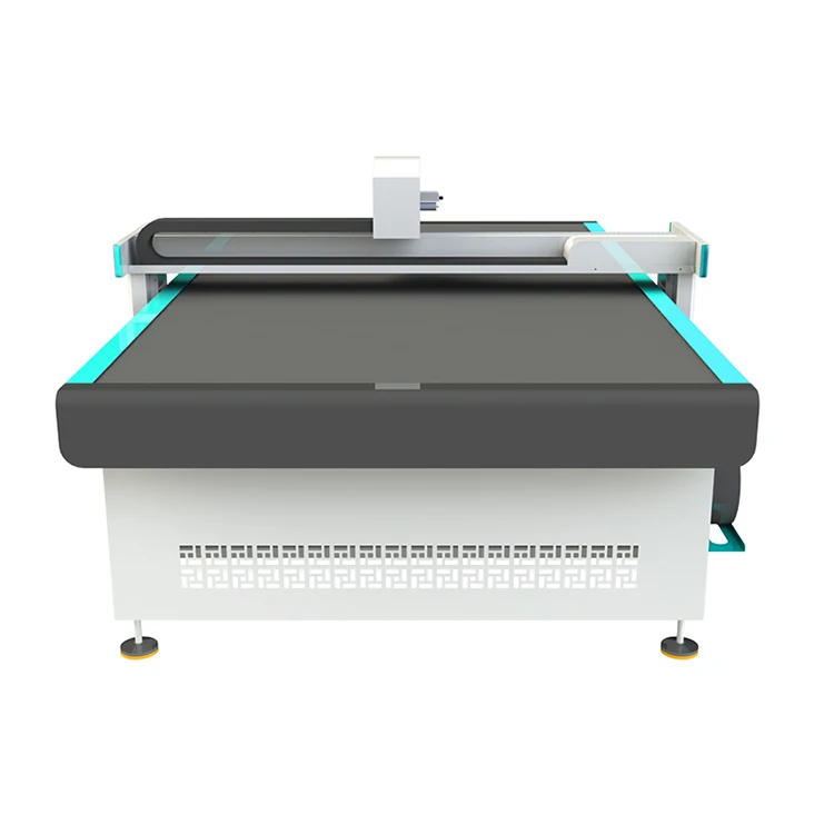
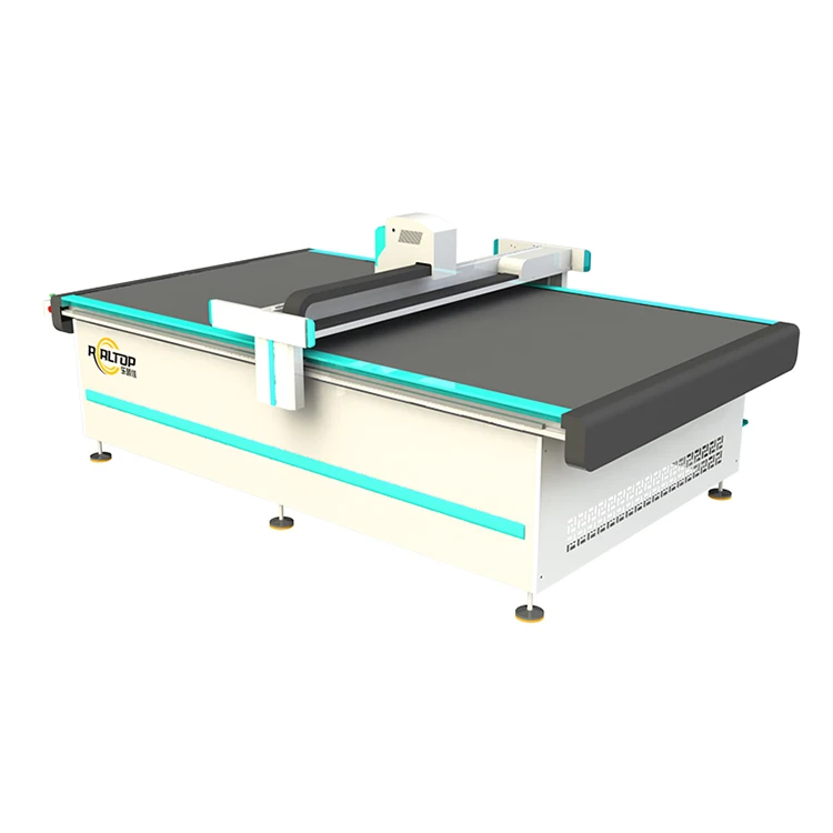
The RTT6080 carries four tool groups — a through-cutting blade, a kiss cutting blade, a creasing wheel and a CCD camera — which together address the bulk of label and folding-carton sample work without requiring a tool change between jobs. The RTT6080 Pro adds a high speed oscillating knife that handles denser substrates up to the thicker end of the envelope, such as multi-ply gasket material or heavier packaging board, where a static drag knife would crush rather than shear the fibers. Selecting between the two variants is not a question of which is better in isolation; it is a question of which substrate density dominates your daily schedule.
CCD Contour Recognition at Production Cadence
For printed stickers and labels, the CCD camera is not simply a positioning aid — it is what determines whether the die cut follows the printed image when the sheet has stretched or skewed during printing. The value of camera-based recognition depends entirely on whether the software can lock onto the registration mark and compensate for rotation within the time window between two consecutive cuts. If your print run uses high-gloss stock or metallic ink that reflects under the sensor light, the mark contrast must be confirmed before the plotter is built, because re-grinding a camera lighting array after delivery is a multi-week correction, not a field adjustment [NEED_CITE: CCD mark contrast requirements on metallized and high-gloss label stock].
Reading the Numbers That Actually Govern Edge Quality
The 0.05 mm positioning accuracy governs how tightly the cut line follows a vector path, and on kiss cutting this tolerance directly affects whether the blade scores the liner or leaves an uncut bridge that makes stripping impossible. The 1500 mm/s maximum cutting speed is a mechanical ceiling that must be derated based on corner density and adhesive tack — a path with many sharp radii on high-tack vinyl will need a lower traverse rate to prevent the material from lifting under the blade. The 3.2 kW rated power drives the servo and vacuum system together; if your workshop runs the plotter alongside other CNC equipment on a shared circuit, voltage sag under simultaneous spindle start-up can cause the servo to lose position mid-job. Confirming whether the 220 V / 380 V rating is single-phase or three-phase at your local frequency, and whether the plug and control language are set before dispatch, avoids the most common commissioning delay I encounter with imported flatbed plotters.
The Cost of Choosing the Wrong Vacuum Zoning
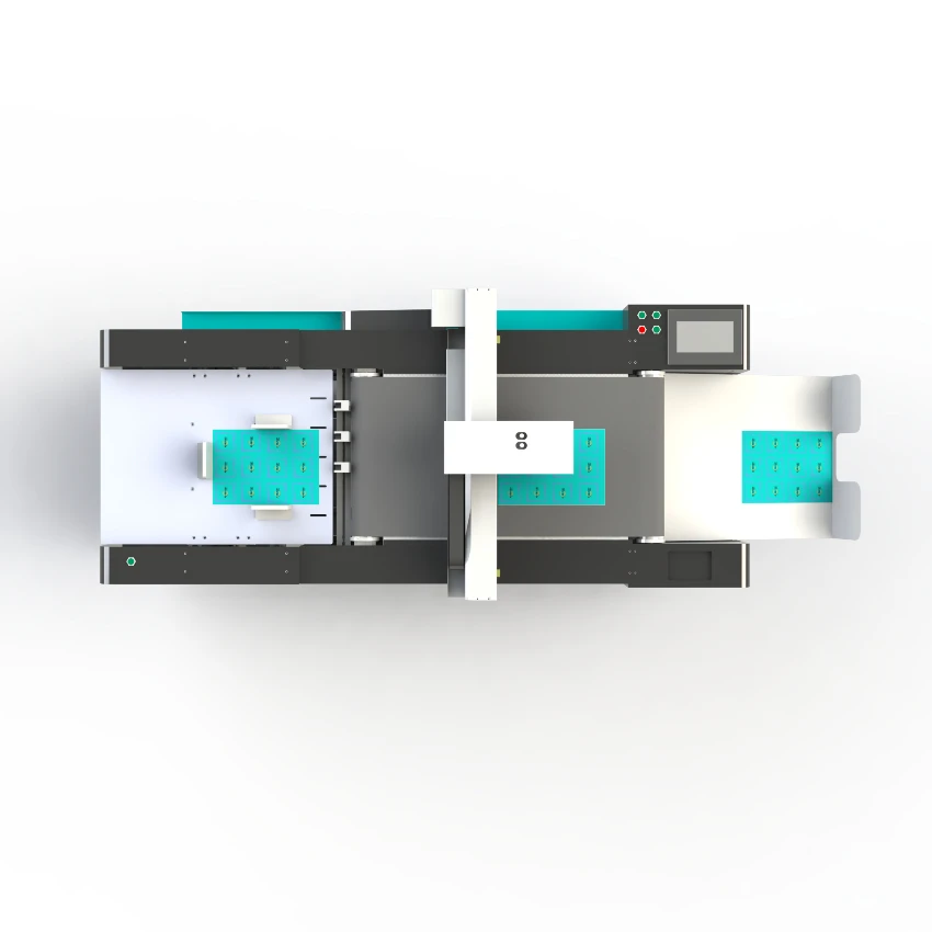
A 600 mm × 800 mm table may appear compact enough that vacuum hold-down is straightforward, yet small sticker sheets and short-run label nests are exactly the format where insufficient vacuum zoning causes the most scrap. When a single zone is opened for a small cut area, the remaining table leaks air and suction pressure drops below the threshold needed to resist blade drag, causing the sheet to shift by fractions of a millimeter — enough to misregister the second color on a two-pass label. This failure mode is rarely visible until the batch is stripped, which is why the vacuum table zoning must be matched to your smallest common nest size, not to the maximum sheet the machine can accept [NEED_CITE: vacuum hold-down zoning on small-format die cutting tables].
What Buying Directly from the Manufacturer Changes
Realtop operates in-house design and production covering both knife and laser cutting technologies, which means the RTT6080 series can be specified against your material rather than forced into a single cutting method. The tool head and table configuration are written per material and production volume before the order is confirmed, not substituted from a stock list after payment. CCD camera positioning for printed contour work is validated on your own file and registration mark format before the machine leaves the factory. Software compatibility — including whether your existing DXF, PLT, PDF or AI nesting workflow transfers without manual re-drawing — is confirmed by file exchange, not by a generic compatibility claim. Voltage, language and specification customization are locked in the order document, and sample cutting on your own material is the step that triggers production, not an afterthought once the machine is already crated.
Documentation & Verification
- Machine specification sheet confirming RTT6080 or RTT6080 Pro tool group assignment
- Electrical schematic with 220 V or 380 V wiring and breaker rating for your site
- Tool head and table configuration list matched to your substrate and nest size
- Sample cutting report on your label stock or packaging board before dispatch
- Software licence and file format compatibility note for DXF, PLT, PDF, AI input
- Spare parts list covering oscillating knife blades and CCD lighting consumables
Installation, Commissioning & Support
- 600 × 800 mm table footprint requires level concrete floor with clearance on three sides
- 3.2 kW rated power demands a dedicated circuit matched to your local 50 Hz supply
- Fully assembled delivery means no gantry alignment required, but vacuum pump connection must be verified on site
- First-run parameter setting includes vacuum zoning calibration for your smallest sticker nest
- Operator training covers CCD mark teaching on your actual print registration format
- Ethernet transfer tested against your workshop network before operator sign-off
What to Send Before Requesting a Quote
To size the RTT6080 or RTT6080 Pro correctly, please provide the substrate type, caliper and adhesive system you will cut most frequently, along with a representative print file so CCD mark contrast can be assessed. Confirm your local voltage and frequency, the control language your operators require, and whether your existing nesting software exports in DXF, PLT, PDF or AI format. If your daily volume runs multiple shifts, note the ambient workshop temperature, as high-tack adhesives behave differently in uncooled environments and may require blade and speed adjustments during commissioning.
Frequently Asked Questions
Q: How do I verify the cutting thickness claim against my specific material?
A: The only reliable method is a sample cutting test on your exact substrate, liner and adhesive stack, run at the speed you plan to use in production. The RTT6080 handles up to 2 mm and the RTT6080 Pro up to 5 mm on the materials tested at the factory, but adhesive stiffness and liner composition change blade behaviour, so the sample report — not the catalogue figure — becomes the contractual reference.
Q: Which tool head do I need for kiss cutting versus through cutting?
A: Kiss cutting requires a dedicated blade with depth stop so the cut penetrates the face stock but leaves the liner intact, while through cutting uses a longer blade and higher downward force. The RTT6080 carries both as separate tool groups, and the choice depends on whether your output is labels to be stripped or die-cut shapes to be fully removed from the matrix.
Q: Will the CCD camera track my printed marks at my required production speed?
A: Camera recognition speed depends on mark contrast, substrate reflectivity and the angular skew your printer introduces. Before order, we run your actual print file through the CCD software to confirm the sensor can lock and compensate within the cut-to-cut cycle time, and we note any lighting adjustment needed for metallic or high-gloss stocks.
Q: What file formats and nesting workflows does the software accept?
A: The control software accepts DXF, PLT, PDF and AI files transferred via Ethernet. If your current workflow uses third-party nesting software, a sample file exchange before order confirms that layer naming, cut order and bridge settings import correctly without manual re-drawing on the plotter controller.
Q: How does the RTT6080 differ from the RTT6080 Pro and which variant fits my daily volume?
A: The RTT6080 carries four tool groups suited to label, sticker and thin carton sample work up to 2 mm. The RTT6080 Pro adds a high speed oscillating knife and extends the thickness envelope to 5 mm, making it the better fit if your daily schedule includes denser packaging board or composite gasket material alongside standard label stock.
Custom tool head mapping — we match knife type, CCD recognition and vacuum zoning to your exact substrate before quoting the RTT-6080 series, so cutting depth and edge quality hold at your production speed rather than only during sample approval.
Technical Specifications
| Parameter | Value |
|---|---|
| Model | RTT6080 / RTT6080 Pro |
| Product Type | CNC Digital Die Cutting Plotter |
| Max Working Area | 600 mm × 800 mm |
| Tool Configuration (RTT6080) | Cutting tool, kiss cutting tool, creasing tool, CCD camera |
| Tool Configuration (RTT6080 Pro) | Cutting tool, kiss cutting tool, creasing tool, CCD camera, high speed oscillating knife |
| Max Cutting Speed | 1500 mm/s (basis not stated in source — confirm material / thickness) |
| Cutting Thickness (RTT6080) | ≤ 2 mm (basis not stated in source — confirm material type) |
| Cutting Thickness (RTT6080 Pro) | ≤ 5 mm (basis not stated in source — confirm material type) |
| Positioning Accuracy | 0.05 mm |
| File Format | DXF, PLT, PDF, AI |
| Transfer Method | Ethernet port |
| Rated Power | 3.2 kW (rated or peak not specified in source) |
| Voltage | 220 V / 380 V, 50 Hz |
| Control System | CNC (source value — verify against manufacturer catalog) |
| Assembly State | Fully assembled (source value — verify against manufacturer catalog) |
Application Suitability
| Application | Material or Output |
|---|---|
| Sticker and label die cutting | Self-adhesive vinyl, PET, BOPP, release liner stock |
| Short-run carton prototyping | Corrugated flute, single-face board, kraft liner |
| Packaging sample making | Folding carton board, greyboard, art paper laminates |
| Advertising and signage prototyping | Self-adhesive film, magnetic sheet, thin PVC board |
| Kiss cutting and creasing | Pressure-sensitive labels, window patching film |
Why the Cutting Thickness Claim Is Where Most Plotter Quotes Fall Apart
When sourcing a CNC Die Cutting Plotter manufacturer, the single number most often misunderstood is maximum cutting thickness, because the figure quoted is almost always a best-case laboratory value on a uniform, compliant material. The only thickness number that matters is the one measured on your actual stock, with your specific liner and adhesive combination, at the speed you intend to run. I have sat in workshops where a plotter was specified on working area alone, then watched the knife stall on a 1.2 mm PVC sticker that the datasheet said would cut at 2 mm, because the adhesive layer and release liner added stiffness the blade could not shear cleanly. The operator then slowed the feed and dropped pressure, which introduced drag marks on the printed face and forced a second pass that doubled cycle time [NEED_CITE: material stiffness and blade drag in pressure-sensitive substrates].
How the Tool Head Range Covers the Sticker-to-Sample Gap
The RTT6080 carries four tool groups — a through-cutting blade, a kiss cutting blade, a creasing wheel and a CCD camera — which together address the bulk of label and folding-carton sample work without requiring a tool change between jobs. The RTT6080 Pro adds a high speed oscillating knife that handles denser substrates up to the thicker end of the envelope, such as multi-ply gasket material or heavier packaging board, where a static drag knife would crush rather than shear the fibers. Selecting between the two variants is not a question of which is better in isolation; it is a question of which substrate density dominates your daily schedule.
CCD Contour Recognition at Production Cadence
For printed stickers and labels, the CCD camera is not simply a positioning aid — it is what determines whether the die cut follows the printed image when the sheet has stretched or skewed during printing. The value of camera-based recognition depends entirely on whether the software can lock onto the registration mark and compensate for rotation within the time window between two consecutive cuts. If your print run uses high-gloss stock or metallic ink that reflects under the sensor light, the mark contrast must be confirmed before the plotter is built, because re-grinding a camera lighting array after delivery is a multi-week correction, not a field adjustment [NEED_CITE: CCD mark contrast requirements on metallized and high-gloss label stock].
Reading the Numbers That Actually Govern Edge Quality
The 0.05 mm positioning accuracy governs how tightly the cut line follows a vector path, and on kiss cutting this tolerance directly affects whether the blade scores the liner or leaves an uncut bridge that makes stripping impossible. The 1500 mm/s maximum cutting speed is a mechanical ceiling that must be derated based on corner density and adhesive tack — a path with many sharp radii on high-tack vinyl will need a lower traverse rate to prevent the material from lifting under the blade. The 3.2 kW rated power drives the servo and vacuum system together; if your workshop runs the plotter alongside other CNC equipment on a shared circuit, voltage sag under simultaneous spindle start-up can cause the servo to lose position mid-job. Confirming whether the 220 V / 380 V rating is single-phase or three-phase at your local frequency, and whether the plug and control language are set before dispatch, avoids the most common commissioning delay I encounter with imported flatbed plotters.
The Cost of Choosing the Wrong Vacuum Zoning
A 600 mm × 800 mm table may appear compact enough that vacuum hold-down is straightforward, yet small sticker sheets and short-run label nests are exactly the format where insufficient vacuum zoning causes the most scrap. When a single zone is opened for a small cut area, the remaining table leaks air and suction pressure drops below the threshold needed to resist blade drag, causing the sheet to shift by fractions of a millimeter — enough to misregister the second color on a two-pass label. This failure mode is rarely visible until the batch is stripped, which is why the vacuum table zoning must be matched to your smallest common nest size, not to the maximum sheet the machine can accept [NEED_CITE: vacuum hold-down zoning on small-format die cutting tables].
What Buying Directly from the Manufacturer Changes
Realtop operates in-house design and production covering both knife and laser cutting technologies, which means the RTT6080 series can be specified against your material rather than forced into a single cutting method. The tool head and table configuration are written per material and production volume before the order is confirmed, not substituted from a stock list after payment. CCD camera positioning for printed contour work is validated on your own file and registration mark format before the machine leaves the factory. Software compatibility — including whether your existing DXF, PLT, PDF or AI nesting workflow transfers without manual re-drawing — is confirmed by file exchange, not by a generic compatibility claim. Voltage, language and specification customization are locked in the order document, and sample cutting on your own material is the step that triggers production, not an afterthought once the machine is already crated.
Documentation & Verification
- Machine specification sheet confirming RTT6080 or RTT6080 Pro tool group assignment
- Electrical schematic with 220 V or 380 V wiring and breaker rating for your site
- Tool head and table configuration list matched to your substrate and nest size
- Sample cutting report on your label stock or packaging board before dispatch
- Software licence and file format compatibility note for DXF, PLT, PDF, AI input
- Spare parts list covering oscillating knife blades and CCD lighting consumables
Installation, Commissioning & Support
- 600 × 800 mm table footprint requires level concrete floor with clearance on three sides
- 3.2 kW rated power demands a dedicated circuit matched to your local 50 Hz supply
- Fully assembled delivery means no gantry alignment required, but vacuum pump connection must be verified on site
- First-run parameter setting includes vacuum zoning calibration for your smallest sticker nest
- Operator training covers CCD mark teaching on your actual print registration format
- Ethernet transfer tested against your workshop network before operator sign-off
What to Send Before Requesting a Quote
To size the RTT6080 or RTT6080 Pro correctly, please provide the substrate type, caliper and adhesive system you will cut most frequently, along with a representative print file so CCD mark contrast can be assessed. Confirm your local voltage and frequency, the control language your operators require, and whether your existing nesting software exports in DXF, PLT, PDF or AI format. If your daily volume runs multiple shifts, note the ambient workshop temperature, as high-tack adhesives behave differently in uncooled environments and may require blade and speed adjustments during commissioning.
Frequently Asked Questions
Q: How do I verify the cutting thickness claim against my specific material?
A: The only reliable method is a sample cutting test on your exact substrate, liner and adhesive stack, run at the speed you plan to use in production. The RTT6080 handles up to 2 mm and the RTT6080 Pro up to 5 mm on the materials tested at the factory, but adhesive stiffness and liner composition change blade behaviour, so the sample report — not the catalogue figure — becomes the contractual reference.
Q: Which tool head do I need for kiss cutting versus through cutting?
A: Kiss cutting requires a dedicated blade with depth stop so the cut penetrates the face stock but leaves the liner intact, while through cutting uses a longer blade and higher downward force. The RTT6080 carries both as separate tool groups, and the choice depends on whether your output is labels to be stripped or die-cut shapes to be fully removed from the matrix.
Q: Will the CCD camera track my printed marks at my required production speed?
A: Camera recognition speed depends on mark contrast, substrate reflectivity and the angular skew your printer introduces. Before order, we run your actual print file through the CCD software to confirm the sensor can lock and compensate within the cut-to-cut cycle time, and we note any lighting adjustment needed for metallic or high-gloss stocks.
Q: What file formats and nesting workflows does the software accept?
A: The control software accepts DXF, PLT, PDF and AI files transferred via Ethernet. If your current workflow uses third-party nesting software, a sample file exchange before order confirms that layer naming, cut order and bridge settings import correctly without manual re-drawing on the plotter controller.
Q: How does the RTT6080 differ from the RTT6080 Pro and which variant fits my daily volume?
A: The RTT6080 carries four tool groups suited to label, sticker and thin carton sample work up to 2 mm. The RTT6080 Pro adds a high speed oscillating knife and extends the thickness envelope to 5 mm, making it the better fit if your daily schedule includes denser packaging board or composite gasket material alongside standard label stock.
商品评价
There are no reviews yet.