



Fast Delivery
Quick, reliable shipping to any location.

Free & easy returns
Return this item by mail or in store within 90 days for a full refund.
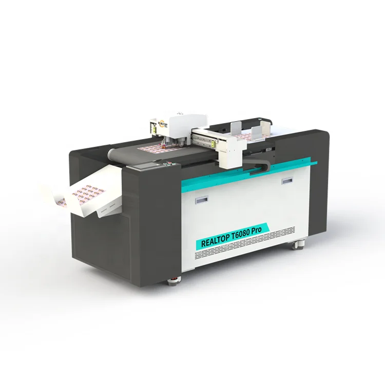
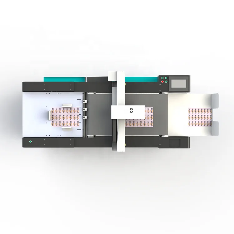
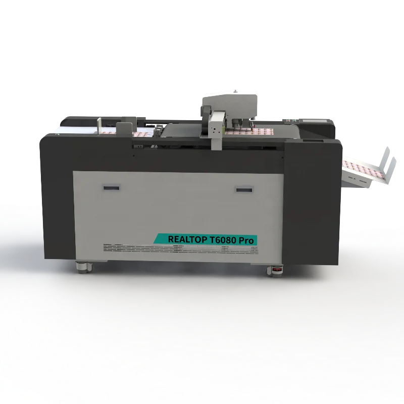
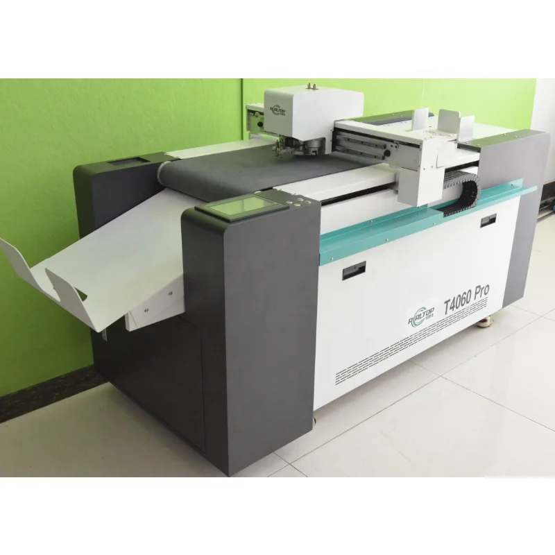
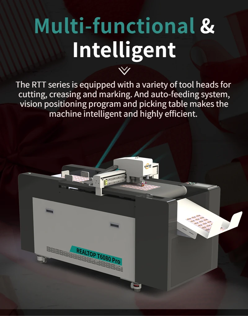
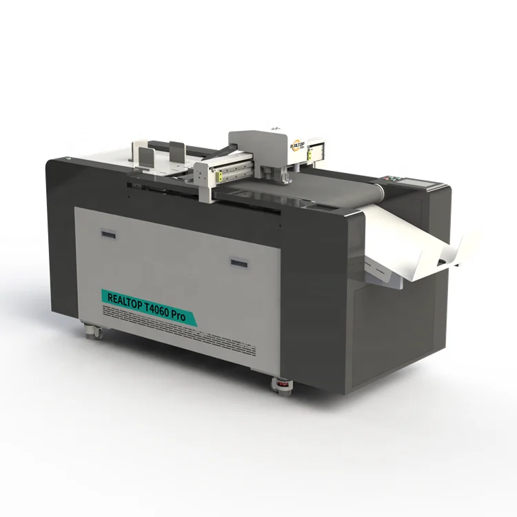
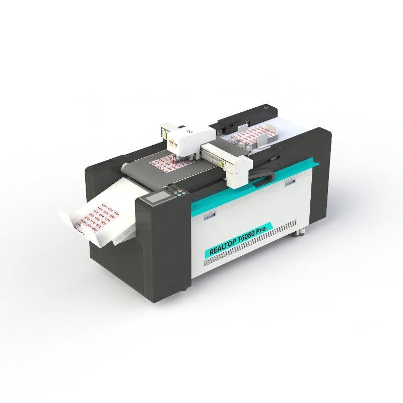
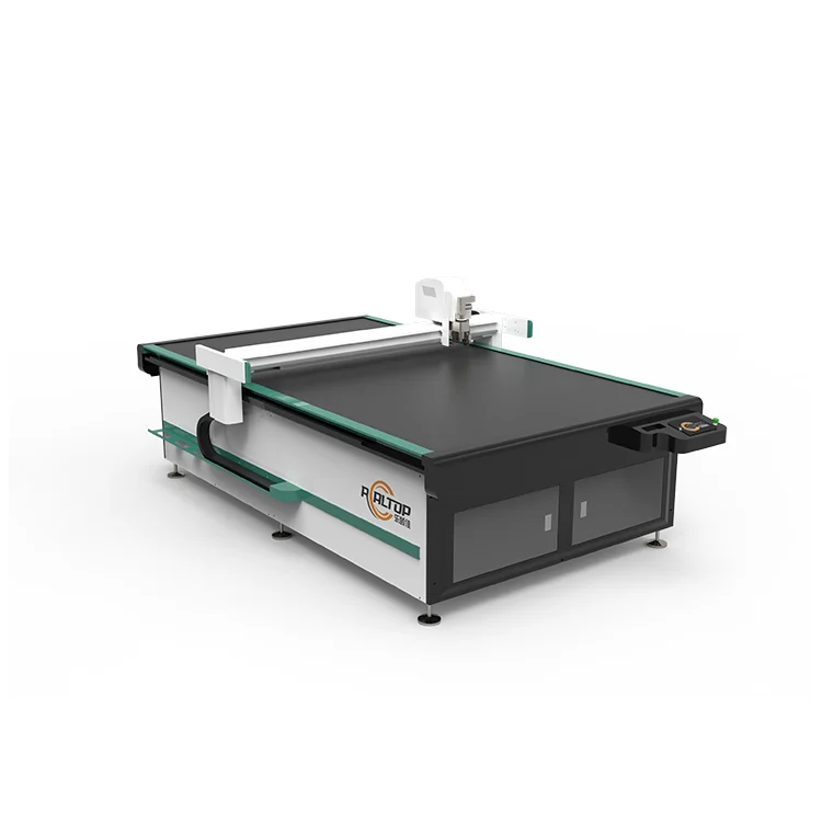
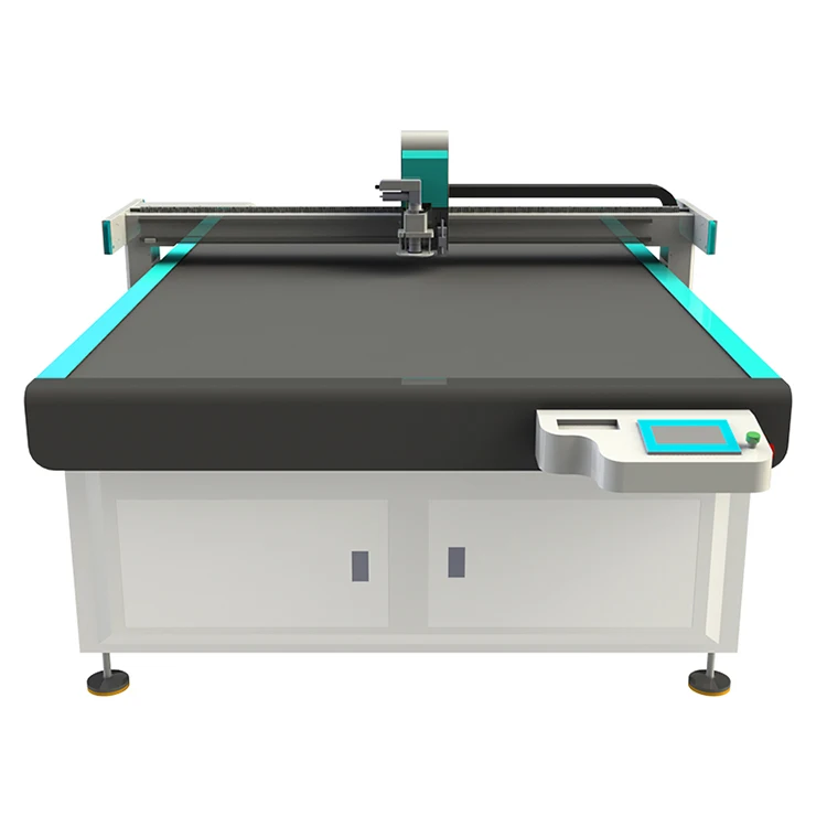
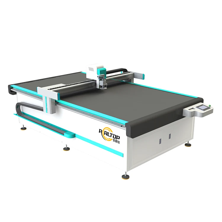
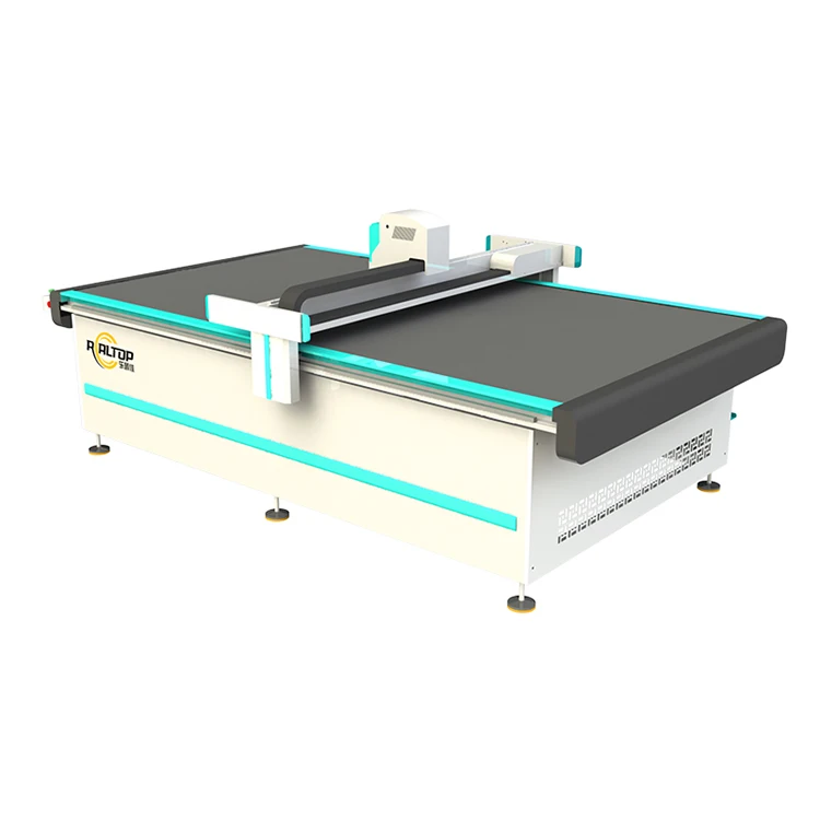
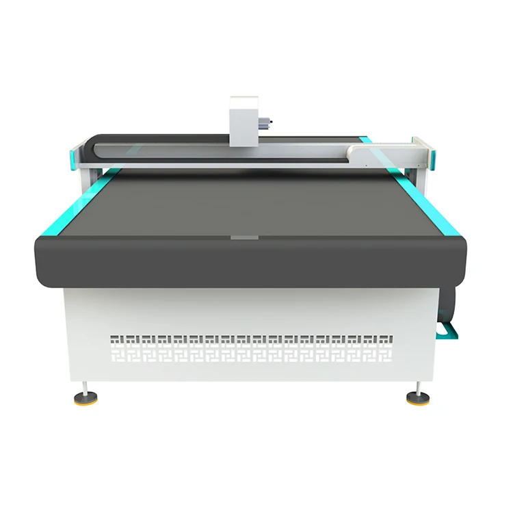
Tool Head and Table Configuration — matched per material and cutting method rather than quoted on working area alone, so the knife, kiss-cut or creasing tool is specified against your actual substrate before the RTT4060 or RTT4060 Pro is built.
Technical Specifications
| Parameter | Value |
|---|---|
| Model | RTT4060 / RTT4060 Pro |
| Product Type | CNC Flatbed Digital Cutting Machine |
| Max Working Area | 400 mm × 600 mm |
| Tool Group | Cutting Tool; Kiss-cutting Tool; Creasing Tool; CCD Camera; High Speed Oscillating Knife (Pro only) |
| Max Cutting Speed | 1500 mm/s (according to the material) |
| Cutting Thickness | <2 mm (RTT4060) / <5 mm (RTT4060 Pro) |
| Positioning Accuracy | 0.05 mm |
| Profile Format | DXF, OLT, PDF, AI |
| Transmission Method | Ethernet port |
| Rated Power | 2.5 kW |
Application Suitability
| Application | Material or Output |
|---|---|
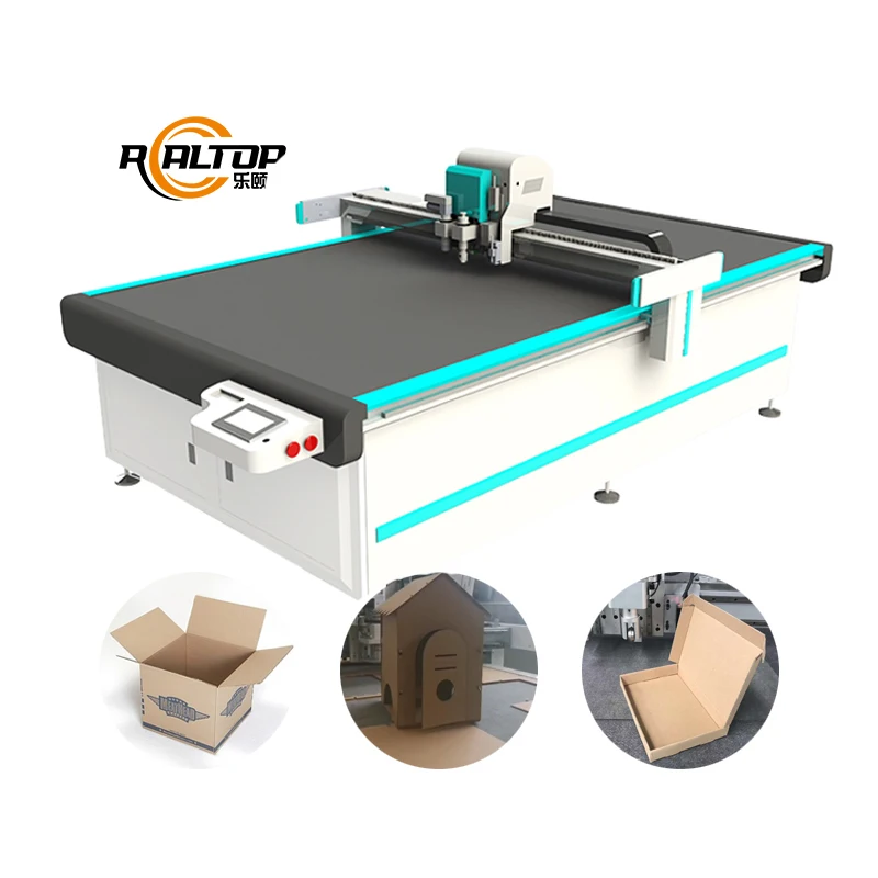
| Packaging and carton sample making | Folding carton mock-ups, white card stock, corrugated liner, short-run die-cut samples |
| Advertising and signage finishing | Vinyl graphics, foam board, printed sheet kiss-cutting and contour trimming |
| Thin non-metal part cutting | Fabric, leather, PVC, foam, gasket materials within thickness limits |
| Printed contour work | Registration mark tracking on pre-printed packaging and signage layouts |
Why the Wrong Tool Head Ruins a Perfectly Good Small-Format Table
A machine quoted on working area alone will cut your material — until it doesn’t.
I once configured an A3-format oscillating knife cutter for a customer doing carton sample work. Standard white card stock ran clean on our test floor, so we shipped it. Two weeks later the customer called — his actual production material was laminated greyboard, not the white card he’d sent for sampling. The blade couldn’t hold an edge through the laminate layer, the crease wheel was crushing rather than scoring, and his daily output dropped by half. Every ragged edge meant a re-cut. That is the hidden cost of specifying a CNC flatbed digital cutting table manufacturer without first confirming what you actually run on a Monday morning. [NEED_CITE: material thickness and tool head selection for digital cutting]
The RTT4060 and RTT4060 Pro address this by locking tool head selection to your specific material stack before the order is placed. The standard RTT4060 handles substrates under 2 mm with cutting, kiss-cutting and creasing tools, while the RTT4060 Pro extends that to under 5 mm and adds a high-speed oscillating knife for denser or layered non-metal sheets.
Matching the Cutting Tool to the Substrate
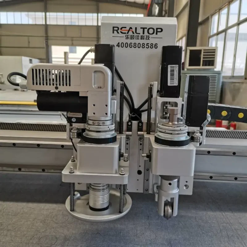
The multi-tool configuration on this table is not a checklist of features — it is a way to avoid forcing one method across every job. A drag knife works for vinyl kiss-cutting on signage overlays but will tear through a folded carton crease line. The creasing wheel scores without cutting through, which matters when a sample maker needs a clean fold on 350 gsm card stock. The high-speed oscillating knife on the Pro model handles thicker foam or multi-ply fabric that a static drag blade would crush or leave ragged. Selecting the right tool head per material is the reason this platform carries all four options on one gantry.
CCD Camera Contour Work at Small Format
Printed contour cutting is where positioning accuracy stops being a spec-sheet number and starts affecting scrap rates. The CCD camera on this table tracks registration marks on pre-printed sheets, adjusting the cut path to compensate for print drift or sheet distortion. On a 400 × 600 mm working area, even a small misalignment is visible on a finished carton sample or a kiss-cut label sheet. The 0.05 mm positioning accuracy keeps the blade on the printed line rather than drifting into the bleed area. [NEED_CITE: CCD camera registration accuracy in digital finishing]
What the Numbers Mean on the Production Floor
The 1500 mm/s maximum cutting speed is qualified by material — a thin vinyl film will allow the head to approach that rate, while a 4 mm foam gasket on the Pro model requires a slower pass to keep the oscillating knife from deflecting. The 2.5 kW rated power covers the vacuum pump, servo drives and spindle together, which matters when you are calculating the dedicated circuit this table needs in a small workshop. The Ethernet transmission port means file transfer happens over your existing network rather than through a USB stick passed between the design desk and the machine. DXF, OLT, PDF and AI file import covers the formats most packaging designers and print finishers already use, so there is no forced software switch at the point of order.
The Cost of Skipping the Sample Cut
When a buyer commits to a compact cutting table without a sample cut on their own material, the first sign of trouble is on the production floor — not in the factory test. Crushed foam cores, delaminated edges on coated board, kiss-cuts that go too deep and score the release liner, or crease lines that crack rather than fold cleanly. Each defect means rework, wasted stock and missed sample deadlines. These are not machine faults in most cases — they are configuration mismatches that a pre-shipment sample cut on the buyer’s actual substrate would have caught. [NEED_CITE: pre-shipment sample testing for digital cutting equipment]
Why Source This Table Through This Build Approach
In-house design covers both the knife cutting platform and the tool head engineering, so the oscillating knife, drag knife and creasing wheel are developed against the same motion system rather than adapted from separate product lines. Tool head and vacuum table zoning are configured per material and sheet size, which prevents the small-part lift problem that happens when suction is spread across a full bed for a 100 mm × 100 mm sample. CCD camera positioning is verified against your printed mark style and color contrast before the order is finalized. Software file format compatibility is confirmed with your existing design files — not assumed. Voltage, plug type and control panel language are locked to your market before shipment, not discovered at the dock.
Documentation & Verification
- Sample cutting report run on your material and thickness before order commitment
- Tool head and table configuration list matched to your substrate stack
- Machine specification sheet with electrical schematic and voltage confirmation
- Software licence with file format compatibility note for DXF, OLT, PDF and AI
- Factory test record documenting positioning accuracy and cut quality on your files
- Operation manual with tool change procedures and maintenance intervals
Installation, Commissioning & Support
- Dedicated 2.5 kW circuit with correct voltage and plug type confirmed before dispatch
- Ethernet port connection to your local network for direct file transfer from design stations
- Vacuum table commissioning with your sheet size to verify hold-down on small parts
- CCD camera calibration against your printed registration marks and color profiles
- Tool head setup training covering blade depth, oscillation rate and creasing wheel pressure
- Spare blade and consumable kit included for initial production runs
What to Send with Your Inquiry
Tell us the material you cut most often, the thickness range and the sheet size you receive from your printer or supplier. Confirm your local voltage and frequency so the electrical system is built for your market. If you run printed contour work, send a sample file or a printed sheet so the CCD camera setup can be validated before the table leaves the factory.
Frequently Asked Questions
Q: How do I confirm the real cutting thickness limit for my material on the RTT4060 versus the RTT4060 Pro?
A: The RTT4060 is rated for materials under 2 mm and the Pro for under 5 mm, but actual cutting depth depends on substrate density and layering. We run a sample cut on your specific material before the order is confirmed, so you see the edge quality and cutting depth on your own stock rather than relying on a generic rating.
Q: Which tool head should I specify for carton sample work versus vinyl kiss-cutting?
A: Carton creasing requires the creasing wheel to score without cutting through, while vinyl kiss-cutting uses the drag knife at controlled depth. Specifying the wrong head produces crushed creases or scored release liners. We configure the tool group based on your primary materials before build.
Q: Will the CCD camera track my printed registration marks at small format sizes?
A: The CCD camera reads registration marks on pre-printed sheets and adjusts the cut path for print drift. On a 400 × 600 mm bed, mark color, size and contrast matter more than on large-format tables. We verify tracking against your actual printed layout before the machine ships.
Q: Can my existing DXF and AI files import directly without changing my design workflow?
A: The system accepts DXF, OLT, PDF and AI formats natively. Before the order, we test your actual design files for layer recognition, cut path assignment and crease line interpretation so there is no software switch or file rework required when the table arrives.
Q: Are voltage, plug type and control language confirmed before the machine ships?
A: Yes. Your local voltage, frequency, plug standard and preferred control panel language are confirmed in the specification sheet before production begins. This avoids the situation where a machine arrives with the wrong plug or a language the operator cannot read.
Tool Head and Table Configuration — matched per material and cutting method rather than quoted on working area alone, so the knife, kiss-cut or creasing tool is specified against your actual substrate before the RTT4060 or RTT4060 Pro is built.
Technical Specifications
| Parameter | Value |
|---|---|
| Model | RTT4060 / RTT4060 Pro |
| Product Type | CNC Flatbed Digital Cutting Machine |
| Max Working Area | 400 mm × 600 mm |
| Tool Group | Cutting Tool; Kiss-cutting Tool; Creasing Tool; CCD Camera; High Speed Oscillating Knife (Pro only) |
| Max Cutting Speed | 1500 mm/s (according to the material) |
| Cutting Thickness | <2 mm (RTT4060) / <5 mm (RTT4060 Pro) |
| Positioning Accuracy | 0.05 mm |
| Profile Format | DXF, OLT, PDF, AI |
| Transmission Method | Ethernet port |
| Rated Power | 2.5 kW |
Application Suitability
| Application | Material or Output |
|---|---|
| Packaging and carton sample making | Folding carton mock-ups, white card stock, corrugated liner, short-run die-cut samples |
| Advertising and signage finishing | Vinyl graphics, foam board, printed sheet kiss-cutting and contour trimming |
| Thin non-metal part cutting | Fabric, leather, PVC, foam, gasket materials within thickness limits |
| Printed contour work | Registration mark tracking on pre-printed packaging and signage layouts |
Why the Wrong Tool Head Ruins a Perfectly Good Small-Format Table
A machine quoted on working area alone will cut your material — until it doesn’t.
I once configured an A3-format oscillating knife cutter for a customer doing carton sample work. Standard white card stock ran clean on our test floor, so we shipped it. Two weeks later the customer called — his actual production material was laminated greyboard, not the white card he’d sent for sampling. The blade couldn’t hold an edge through the laminate layer, the crease wheel was crushing rather than scoring, and his daily output dropped by half. Every ragged edge meant a re-cut. That is the hidden cost of specifying a CNC flatbed digital cutting table manufacturer without first confirming what you actually run on a Monday morning. [NEED_CITE: material thickness and tool head selection for digital cutting]
The RTT4060 and RTT4060 Pro address this by locking tool head selection to your specific material stack before the order is placed. The standard RTT4060 handles substrates under 2 mm with cutting, kiss-cutting and creasing tools, while the RTT4060 Pro extends that to under 5 mm and adds a high-speed oscillating knife for denser or layered non-metal sheets.
Matching the Cutting Tool to the Substrate
The multi-tool configuration on this table is not a checklist of features — it is a way to avoid forcing one method across every job. A drag knife works for vinyl kiss-cutting on signage overlays but will tear through a folded carton crease line. The creasing wheel scores without cutting through, which matters when a sample maker needs a clean fold on 350 gsm card stock. The high-speed oscillating knife on the Pro model handles thicker foam or multi-ply fabric that a static drag blade would crush or leave ragged. Selecting the right tool head per material is the reason this platform carries all four options on one gantry.
CCD Camera Contour Work at Small Format
Printed contour cutting is where positioning accuracy stops being a spec-sheet number and starts affecting scrap rates. The CCD camera on this table tracks registration marks on pre-printed sheets, adjusting the cut path to compensate for print drift or sheet distortion. On a 400 × 600 mm working area, even a small misalignment is visible on a finished carton sample or a kiss-cut label sheet. The 0.05 mm positioning accuracy keeps the blade on the printed line rather than drifting into the bleed area. [NEED_CITE: CCD camera registration accuracy in digital finishing]
What the Numbers Mean on the Production Floor
The 1500 mm/s maximum cutting speed is qualified by material — a thin vinyl film will allow the head to approach that rate, while a 4 mm foam gasket on the Pro model requires a slower pass to keep the oscillating knife from deflecting. The 2.5 kW rated power covers the vacuum pump, servo drives and spindle together, which matters when you are calculating the dedicated circuit this table needs in a small workshop. The Ethernet transmission port means file transfer happens over your existing network rather than through a USB stick passed between the design desk and the machine. DXF, OLT, PDF and AI file import covers the formats most packaging designers and print finishers already use, so there is no forced software switch at the point of order.
The Cost of Skipping the Sample Cut
When a buyer commits to a compact cutting table without a sample cut on their own material, the first sign of trouble is on the production floor — not in the factory test. Crushed foam cores, delaminated edges on coated board, kiss-cuts that go too deep and score the release liner, or crease lines that crack rather than fold cleanly. Each defect means rework, wasted stock and missed sample deadlines. These are not machine faults in most cases — they are configuration mismatches that a pre-shipment sample cut on the buyer’s actual substrate would have caught. [NEED_CITE: pre-shipment sample testing for digital cutting equipment]
Why Source This Table Through This Build Approach
In-house design covers both the knife cutting platform and the tool head engineering, so the oscillating knife, drag knife and creasing wheel are developed against the same motion system rather than adapted from separate product lines. Tool head and vacuum table zoning are configured per material and sheet size, which prevents the small-part lift problem that happens when suction is spread across a full bed for a 100 mm × 100 mm sample. CCD camera positioning is verified against your printed mark style and color contrast before the order is finalized. Software file format compatibility is confirmed with your existing design files — not assumed. Voltage, plug type and control panel language are locked to your market before shipment, not discovered at the dock.
Documentation & Verification
- Sample cutting report run on your material and thickness before order commitment
- Tool head and table configuration list matched to your substrate stack
- Machine specification sheet with electrical schematic and voltage confirmation
- Software licence with file format compatibility note for DXF, OLT, PDF and AI
- Factory test record documenting positioning accuracy and cut quality on your files
- Operation manual with tool change procedures and maintenance intervals
Installation, Commissioning & Support
- Dedicated 2.5 kW circuit with correct voltage and plug type confirmed before dispatch
- Ethernet port connection to your local network for direct file transfer from design stations
- Vacuum table commissioning with your sheet size to verify hold-down on small parts
- CCD camera calibration against your printed registration marks and color profiles
- Tool head setup training covering blade depth, oscillation rate and creasing wheel pressure
- Spare blade and consumable kit included for initial production runs
What to Send with Your Inquiry
Tell us the material you cut most often, the thickness range and the sheet size you receive from your printer or supplier. Confirm your local voltage and frequency so the electrical system is built for your market. If you run printed contour work, send a sample file or a printed sheet so the CCD camera setup can be validated before the table leaves the factory.
Frequently Asked Questions
Q: How do I confirm the real cutting thickness limit for my material on the RTT4060 versus the RTT4060 Pro?
A: The RTT4060 is rated for materials under 2 mm and the Pro for under 5 mm, but actual cutting depth depends on substrate density and layering. We run a sample cut on your specific material before the order is confirmed, so you see the edge quality and cutting depth on your own stock rather than relying on a generic rating.
Q: Which tool head should I specify for carton sample work versus vinyl kiss-cutting?
A: Carton creasing requires the creasing wheel to score without cutting through, while vinyl kiss-cutting uses the drag knife at controlled depth. Specifying the wrong head produces crushed creases or scored release liners. We configure the tool group based on your primary materials before build.
Q: Will the CCD camera track my printed registration marks at small format sizes?
A: The CCD camera reads registration marks on pre-printed sheets and adjusts the cut path for print drift. On a 400 × 600 mm bed, mark color, size and contrast matter more than on large-format tables. We verify tracking against your actual printed layout before the machine ships.
Q: Can my existing DXF and AI files import directly without changing my design workflow?
A: The system accepts DXF, OLT, PDF and AI formats natively. Before the order, we test your actual design files for layer recognition, cut path assignment and crease line interpretation so there is no software switch or file rework required when the table arrives.
Q: Are voltage, plug type and control language confirmed before the machine ships?
A: Yes. Your local voltage, frequency, plug standard and preferred control panel language are confirmed in the specification sheet before production begins. This avoids the situation where a machine arrives with the wrong plug or a language the operator cannot read.
商品评价
There are no reviews yet.